Frequency-variable pulse-width-modulation motor drive circuit capable of operating under different pwm frequencies

a technology of pulse width and motor drive, which is applied in the direction of motor/generator/converter stopper, electronic commutator, dynamo-electric converter control, etc., can solve the problem of unnecessarily operating at full speed of the motor, generating an increased amount of air noise and vibration, and unable to achieve greater operational heat dissipation effect, etc. problem, to achieve the effect of improving the waveform

Inactive Publication Date: 2007-09-27
SUNONWEALTH ELECTRIC MACHINE IND
View PDF9 Cites 7 Cited by
  • Summary
  • Abstract
  • Description
  • Claims
  • Application Information

AI Technical Summary

Benefits of technology

[0016] The primary objective of this invention is to provide a frequency-variable PWM motor drive circuit capable of operating under different PWM frequencies, wherein a compensation unit connects between a drive IC member and a PWM converter circuit. The compensation unit can improve a waveform supplied from the PWM converter circuit so that a distortion of the ratio of a peak to a wavelength of the waveform is attenuated. Accordingly, the PWM motor drive circuit is so configured to be suitable for applying in various frequencies of PWM signals.
[0017] The secondary objective of this invention is to provide the frequency-variable PWM motor drive circuit capable of operating under different PWM frequencies, wherein a compensation unit connects between a drive IC member and a PWM converter circuit. The compensation unit can prevent distortions of the waveform from directly supplying to the drive IC member. Accordingly, the PWM motor drive circuit is so configured to steady motor speeds while applying in various frequencies of PWM signals.
[0018] The frequency-variable PWM motor drive circuit in accordance with an aspect of the present invention includes a drive IC member, a Hall IC member, a PWM converter circuit and a compensation unit. The drive IC member electrically connects with the Hall IC member, the drive IC member further includes a pin electrically connected with the compensation unit and the PWM converter circuit. The PWM converter circuit has a PWM input pin to receive a PWM signal, and converts it into a voltage signal. The compensation unit connects between the pin of the drive IC member and the PWM converter circuit. In operation, the compensation unit can improve a waveform of the voltage signal supplied from the PWM converter circuit, and then output it to the pin of the drive IC member. Consequently, the drive IC member can be steadily operated at predetermined motor speeds under various frequencies of the PWM signals.

Problems solved by technology

However, there is no greater amount of operational heat for dissipation.
This results in the motor unnecessarily operating at full speed (i.e. top speed) that generates an increased amount of air noise and vibration.
Furthermore, the motor occurs an increased amount of abrasion among motor components that may shorten the longevity of the motor.
However, ambient heat generated from a heat source is lower than a high temperature when the motor is started.
Therefore, it is undesirable to permit the drive IC member 10 to increase the speed of the motor reaching 6,000 rpm in the high-speed mode that is unsuitable for the need of normal usage or an improper usage of the motor due to a waste of power consumption.
This results in an incorrect motor speed relative to a predetermined motor speed due to duty cycle less than 50%.
Frankly, the conventional PWM converter circuit 12 is only suitable for applying in the frequencies of the PWM signals lower than 100 Hz, and is unsuitable for applying in the frequencies higher than 100 Hz, other higher frequencies, or the frequency of 100 KHz.

Method used


Image

  • Frequency-variable pulse-width-modulation motor drive circuit capable of operating under different pwm frequencies
  • Frequency-variable pulse-width-modulation motor drive circuit capable of operating under different pwm frequencies
  • Frequency-variable pulse-width-modulation motor drive circuit capable of operating under different pwm frequencies

Examples


Embodiment Construction

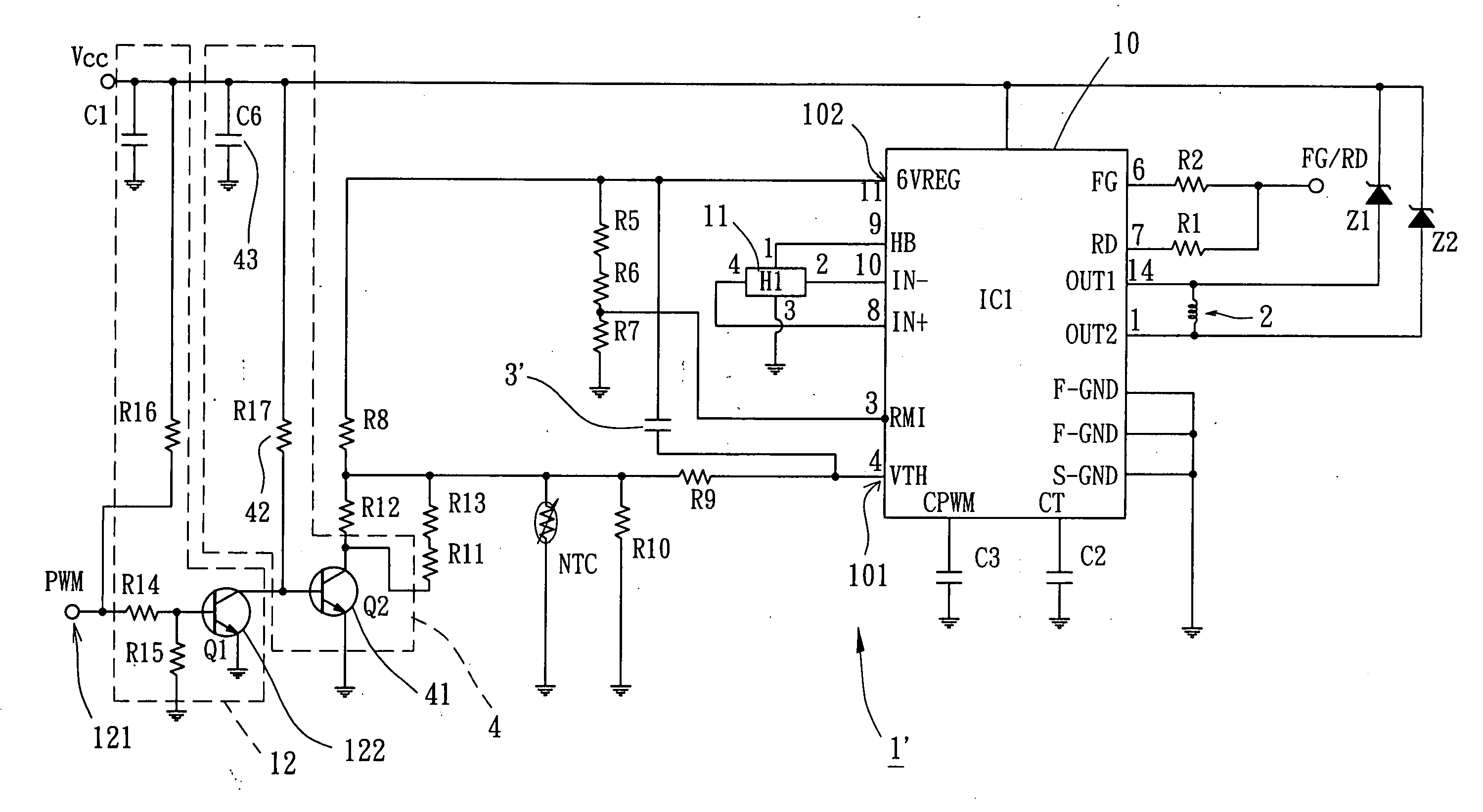
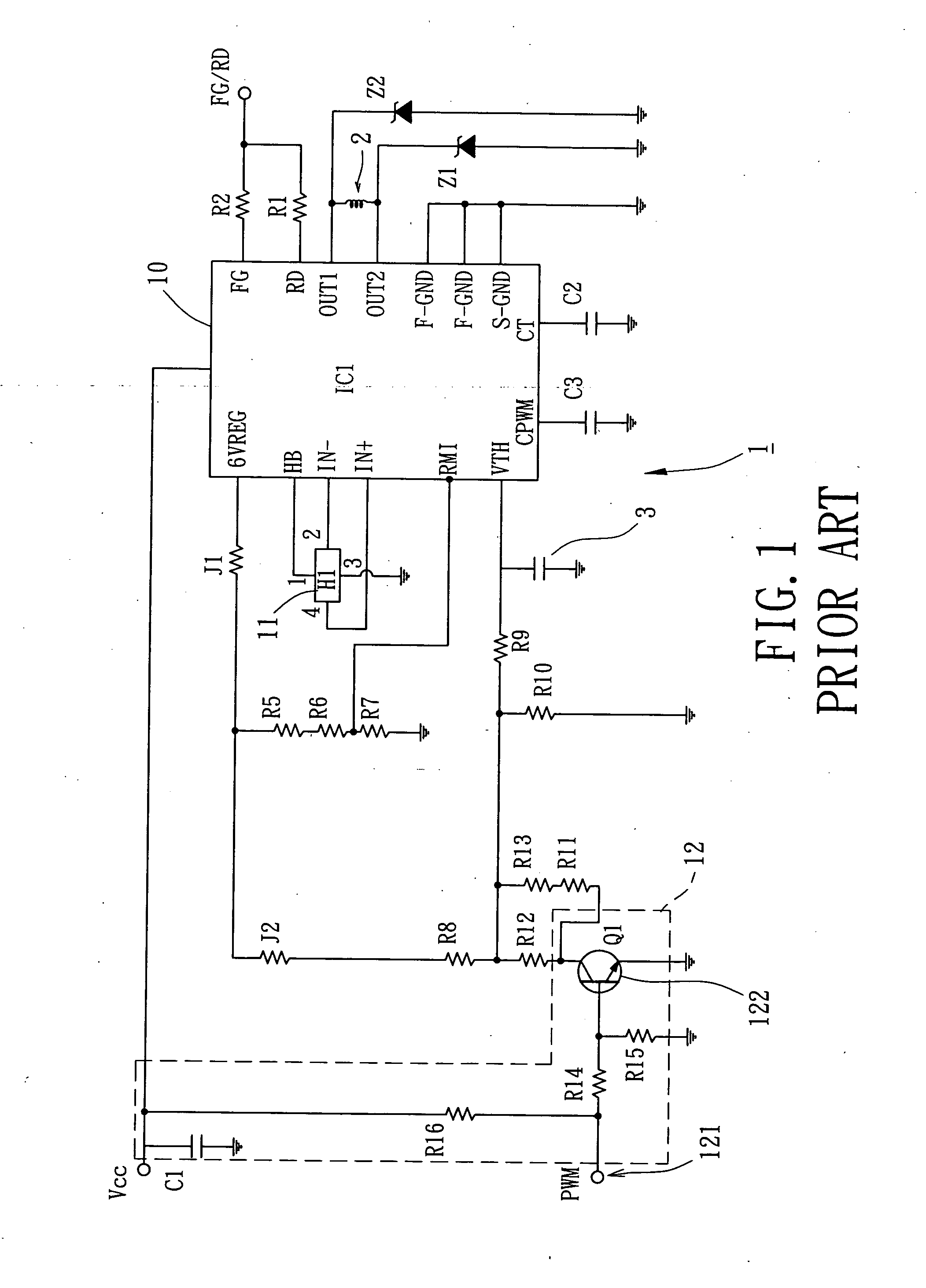
[0033] Turning now to FIG. 4, a schematic circuitry diagram illustrating a frequency-variable PWM motor drive circuit in accordance with a preferred embodiment of the present invention is provided. It should be understood that reference numerals of the PWM motor drive circuit of the preferred embodiment of the present invention have applied the identical numerals of the conventional PWM motor drive circuit, as shown in FIG. 1.

[0034] Still referring to FIG. 4, the frequency-variable PWM motor drive circuit 1′ electrically connects with a motor coil 2 so as to carry out alternatively magnetizing the motor coil 2. In a preferred embodiment, the motor coil 2 can be selected from a group consisting of a single-phase coil, a double-phase coil and a three-phase coil. Typically, the frequency-variable PWM motor drive circuit 1′ includes a drive IC member 10, a Hall IC member 11, a PWM converter circuit 12, at least one capacitor 3′ and a compensation unit 4. In operation, the frequency-var...


PUM


Abstract

A frequency-variable PWM motor drive circuit includes a drive IC member, a Hall IC member, a PWM converter circuit and a compensation unit. The drive IC member electrically connects with the Hall IC member, the drive IC member further includes a pin electrically connected with the compensation unit and the PWM converter circuit. The PWM converter circuit has a PWM input pin to receive a PWM signal, and converts it into a voltage signal. The compensation unit connects between the pin of the drive IC member and the PWM converter circuit. In operation, the compensation unit can improve a waveform of the voltage signal supplied from the PWM converter circuit, and then output it to the pin of the drive IC member. Consequently, the drive IC member can be steadily operated at predetermined motor speeds under various frequencies of the PWM signals.

Description

BACKGROUND OF THE INVENTION [0001] 1. Field of the Invention [0002] The present invention relates to a frequency-variable PWM (Pulse Width Modulation) motor drive circuit capable of operating under different PWM frequencies. More particularly, the present invention relates to the frequency-variable PWM modulation motor drive circuit having a compensation unit connected between a drive IC member and a PWM converter circuit such that the PWM converter circuit is capable of operating under different PWM frequencies. [0003] 2. Description of the Related Art [0004] Referring to FIG. 1, a conventional PWM motor includes a PWM motor drive circuit 1 electrically connected with a motor coil 2 so as to carry out alternatively magnetizing (energizing) the motor coil 2. The alternatively magnetized motor coil 2 can drive a motor rotor (not shown) to turn with respect to a motor stator (not shown) of the PWM motor. Typically, the PWM motor drive circuit 1 includes a drive IC member 10, a Hall IC...

Claims


Application Information

Patent Timeline
Patent Type & Authority Applications(United States)
IPC IPC(8): H02P7/29
CPCH02P6/16H02P6/08
Inventor HORNG, ALEXCHENG, CHUNG-KENLO, PEI-WEI
Owner SUNONWEALTH ELECTRIC MACHINE IND
Why Eureka
Try Eureka