Precision oscillator having improved temperature coefficient control

a technology of temperature coefficient control and precision oscillator, which is applied in the field of precision oscillator, can solve the problems of requiring a more complex external assembly, and using an on-chip free-running oscillator, built entirely of integrated components, e.g. inductors, etc., to achieve the effect of reducing the cost of the external assembly

Inactive Publication Date: 2007-10-18
SILICON LAB INC
View PDF4 Cites 31 Cited by
  • Summary
  • Abstract
  • Description
  • Claims
  • Application Information

AI Technical Summary

Problems solved by technology

The use of an on-chip free-running oscillator, built entirely of integrated components, e.g. transistors, resistors, capacitors, inductors, etc., but no crystal, will typically not be acceptable due to temperature drift, manufacturing tolerances, supply voltage variation, etc.
On the other hand, crystals are typically external devices, thus requiring a more complex external assembly.
A typical two-terminal integrated resistor consists of a series connection of three parts: a desired “pure” resistor part which is typically well-controlled during manufacturing, and two undesired parasitic “end” resistor parts, one on each side, which are typically very poorly controlled during manufacturing.
When turned on, a transistor used as a switch has an unwanted series on-resistance associated with it, which suffers from a high, nonlinear, and poorly-controlled temperature coefficient.
These sub-threshold leakage currents are especially problematic in modern submicron CMOS processes, e.g. 0.18 micron processes.
Unfortunately, there exists a fundamental physical tradeoff between on-resistance and sub-threshold leakage which cannot be avoided by simply changing the size of the transistor: making the sub-threshold leakage smaller makes the on-resistance larger, and vice versa.
When the temperature coefficients of the resistors in the voltage reference circuit are degraded, so too is the temperature coefficient of the overall oscillator circuit, resulting in poor frequency stability of the oscillator.

Method used


Image

  • Precision oscillator having improved temperature coefficient control
  • Precision oscillator having improved temperature coefficient control
  • Precision oscillator having improved temperature coefficient control

Examples


Embodiment Construction

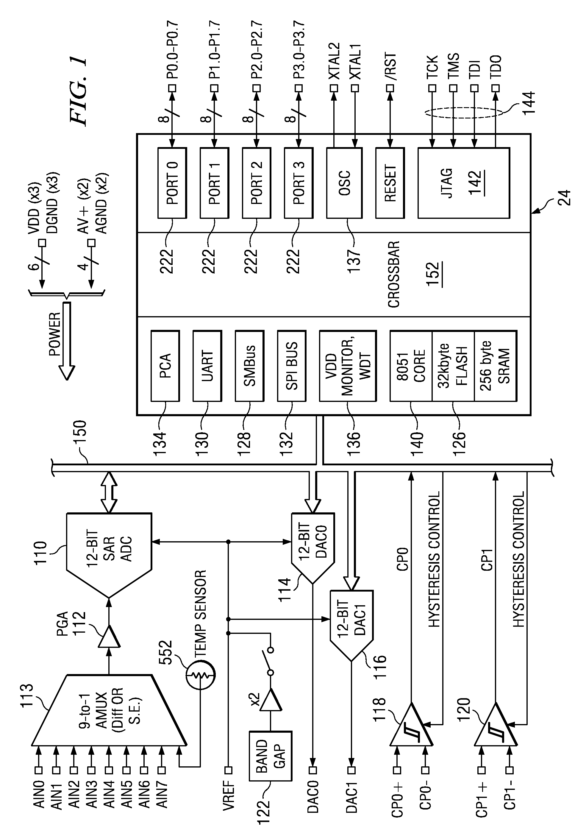
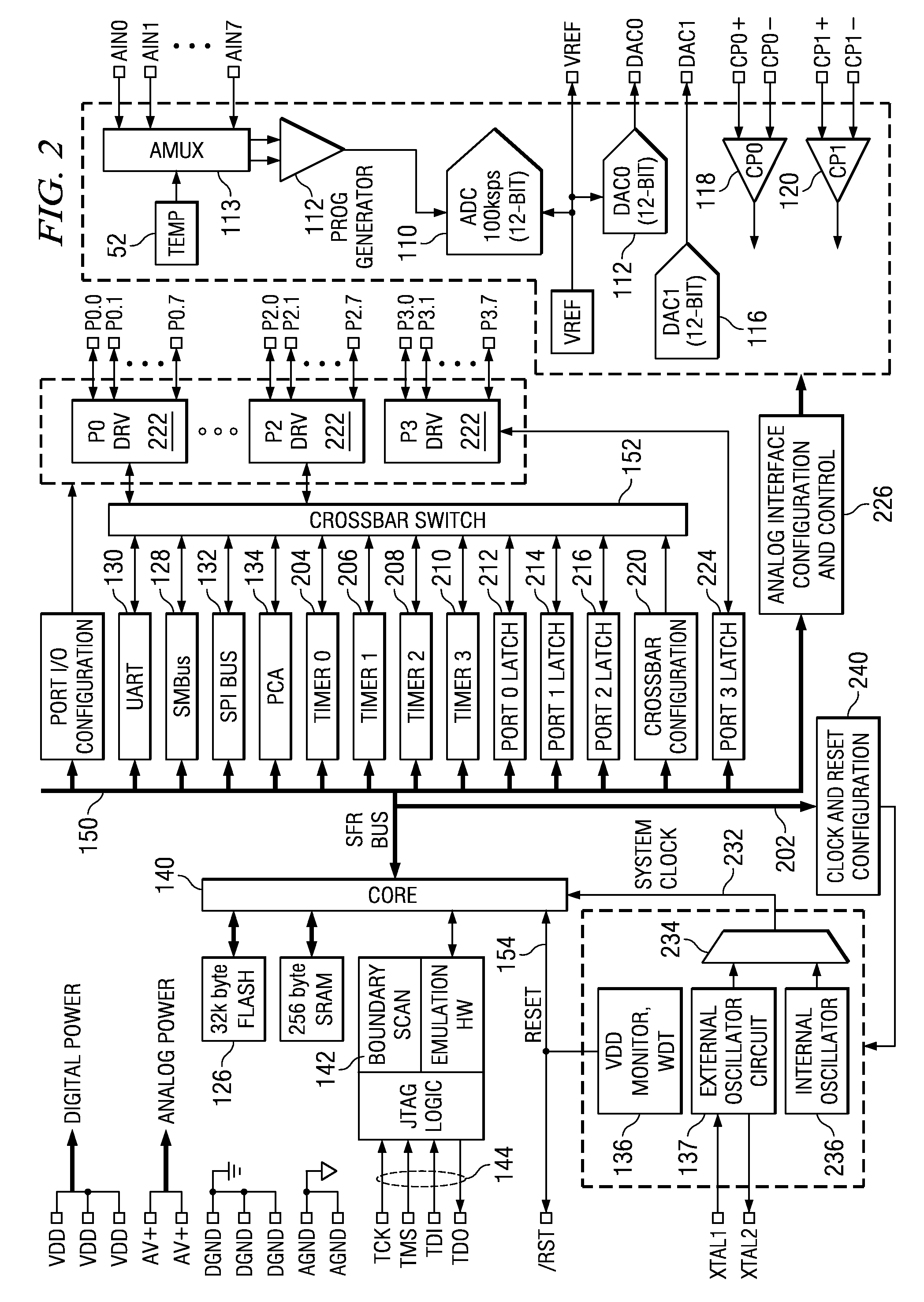
[0046]Referring now to FIG. 1, there is illustrated an integrated circuit that is comprised of a fully integrated mixed-signal System on a Chip with a true 12-bit multi-channel ADC 110 with a programmable gain pre-amplifier s12,two 12-bit DACs 114 and 116, two voltage comparators 118 and 120, a voltage reference 22, and an 8051-compatible microcontroller corel 24 with 32 kbytes of FLASH memory 126. There is also provided an I2C / SMBUS 128, a UART 130, and an SPI 132 serial interface 140 implemented in hardware (not “bit-banged” in user software) as well as a Programmable Counter / Timer Array (PCA) 134 with five capture / compare modules. There are also 32 general purpose digital Port I / Os. The analog side further includes a multiplexer 113 as operable to interface eight analog inputs to the programmable amplifier 112 and to the ADC 110.

[0047]With an on-board VDD monitor 136, WDT, and clock oscillator 137, the integrated circuit is a stand-alone System on a Chip. The MCU effectively conf...


PUM


Abstract

A free running clock circuit includes a switching circuit for switching between first and second logic states at a predetermined frequency based upon a trip voltage the switching circuit has a programmable temperature profile associated therewith. The switching circuit includes a comparator circuit that has first and second comparators. The first and second comparators have a reference input connected to receive the trip voltage, and the output of the comparators change logic states between a first logic state and a second logic state when the other input of the comparator passes the trip voltage. The first and second comparators have a programmable offset voltage enabling programming of the programmable voltage supply profile of the switching circuit. An RC timing circuit defines when the outputs of the comparators switch between the first and second logic states by providing a feedback to the other inputs of the two comparators. A temperature compensated trip voltage generator outputs a defined trip voltage that is compensated over temperature to offset the temperature profile of said switching circuit to provide an overall temperature compensated operation for said free running clock circuit.

Description

CROSS-REFERENCE TO RELATED APPLICATIONS[0001]This present application is related to U.S. patent application Ser. No. 09 / 885,459, filed Jun. 19, 2001 and entitled “FIELD PROGRAMMABLE MD(ED-SIGNAL INTEGRATED CIRCUIT” (Atty. Dkt. No. CYGL-25,768), which is incorporated herein by reference; U.S. patent application Ser. No. 10 / 244,728, entitled “CLOCK RECOVERY METHOD FOR BURSTY COMMUNICATIONS,” Atty. Dkt. CYGL-26,068, which is also incorporated herein by reference; and U.S. patent application Ser. No. 10 / 244,344, entitled “PRECISION OSCILLATOR FOR AN ASYNCHRONOUS TRANSMISSION SYSTEM” (Atty. Dkt. No. CYGL-26,116), which is incorporated herein by reference.TECHNICAL FIELD OF THE INVENTION[0002]The present invention relates to precision oscillators, and more particularly, to the latch and comparator circuitry of a precision oscillator.BACKGROUND OF THE INVENTION[0003]Universal, asynchronous transmitter / receivers (UARTs) are interface circuits, generally in the form of integrated circuit chi...

Claims


Application Information

Patent Timeline
Patent Type & Authority Applications(United States)
IPC IPC(8): H03L1/00
CPCH03K3/011H03K3/354H03K3/0231
Inventor NERVEGNA, LOUIS J.
Owner SILICON LAB INC
Why Eureka
Try Eureka