Resonance-induced sensitivity enhancement method for conductivity sensors

a conductivity sensor and enhancement method technology, applied in the field of conductivity sensors, can solve the problems of reducing the sensitivity of the capacitively-coupled contactless conductivity detector (csup>4/sup>d), limiting the application of the conventional conductivity detector, and the decrease of the double layer capacitance of the electrode, etc., to achieve the effect of increasing the sensitivity of the capacitively-coupled contactless conductivity detector and enhancing the sensitivity

Inactive Publication Date: 2007-10-25
CALIFORNIA INST OF TECH
View PDF7 Cites 30 Cited by
  • Summary
  • Abstract
  • Description
  • Claims
  • Application Information

AI Technical Summary

Benefits of technology

[0007] In one aspect, the invention relates to a method of increasing the sensitivity of a capacitively-coupled contactless conductivity detector. The method comprises the steps of: providing a capacitively-coupled contactless conductivity detector operable at an operation frequency W0, the capacitively-coupled contactless conductivity detector comprising at least two electrodes disposed about a closed channel of an HPLC apparatus and spaced apart from each other, the capacitively-coupled contactless conductivity detector having a capacitance CW between the sensing electrode and a solution in the closed channel, a parasitic capacitance CP between the at least two electrodes, and a solution resistance RS between the at least two electrodes; and providing a inductor having an inductance LS and an internal serial resistance of RLS in parallel

Problems solved by technology

A serious problem in AC impedance sensing of particles (e.g., blood cells in plasma) with micro electrodes is that with the shrinking of electrode surface area the electrode double layer capacitance decreases.
For example, the sensitivity of the capacitively-coupled contactless conductivity detector (C4D) is inferi

Method used


Image

  • Resonance-induced sensitivity enhancement method for conductivity sensors
  • Resonance-induced sensitivity enhancement method for conductivity sensors
  • Resonance-induced sensitivity enhancement method for conductivity sensors

Examples


Embodiment Construction

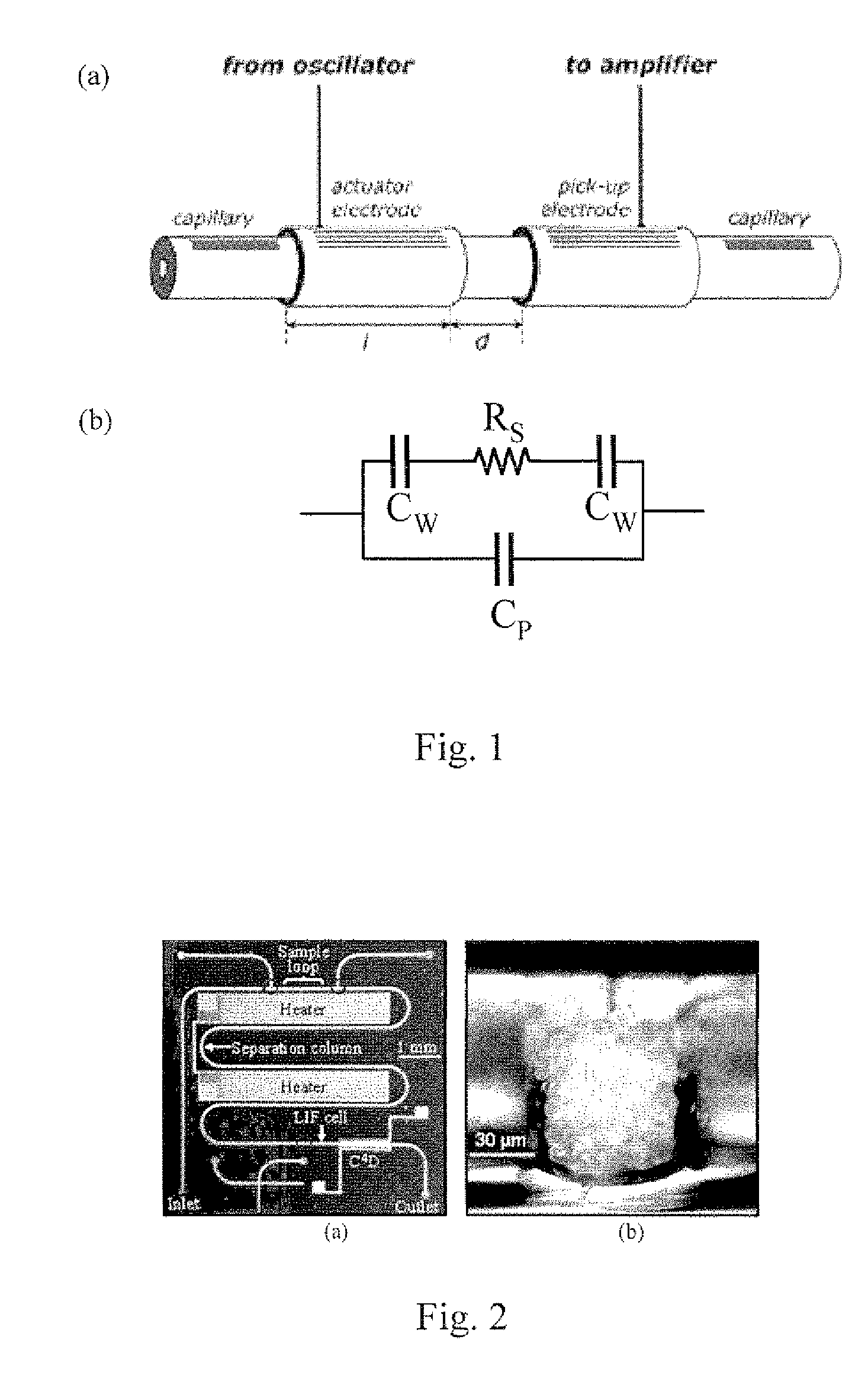
[0038] Capacitively-coupled contactless conductivity detection (C4D) is a technique used frequently in LC and CE. In the conventional method, the sensing electrodes are put outside of a flow channel, such as the separation column in LC, as shown in FIG. 1(a) to avoid electrode corrosion by the solution flowing in the channel, such as an electrolyte solution. In the equivalent circuit model of C4D, shown in FIG. 1(b), CW is the capacitance between the sensing electrode and the solution where the capillary wall material is the capacitor dielectric. CP is the parasitic capacitance between the electrodes. RS is the solution resistance between the electrodes.

[0039] The sensitivity degradation of conventional C4D is exacerbated when the sensor is built in micro scale devices such as those constructed using microfabrication technology such as MEMS. For example, FIG. 2(a) shows a temperature-controlled microchip HPLC (high performance liquid chromatography) system fabricated in the Caltech...


PUM


Abstract

Methods and systems for improving the sensitivity of a variety of conductivity sensing devices, in particular capacitively-coupled contactless conductivity detectors. A parallel inductor is added to the conductivity sensor. The sensor with the parallel inductor is operated at a resonant frequency of the equivalent circuit model. At the resonant frequency, parasitic capacitances that are either in series or in parallel with the conductance (and possibly a series resistance) is substantially removed from the equivalent circuit, leaving a purely resistive impedance. An appreciably higher sensor sensitivity results. Experimental verification shows that sensitivity improvements of the order of 10,000-fold are possible. Examples of detecting particulates with high precision by application of the apparatus and methods of operation are described.

Description

CROSS-REFERENCE TO RELATED APPLICATIONS [0001] This application claims priority to and the benefit of co-pending U.S. provisional patent application Ser. No. 60 / 789,510, filed Apr. 5, 2006, which application is incorporated herein by reference in its entirety.STATEMENT REGARDING FEDERALLY FUNDED RESEARCH OR DEVELOPMENT [0002] The invention described herein was made in the performance of work under National Science Foundation Grant No. CCR-0121778 and under NASA Grant No. NCC 9-58, and is subject to the provisions of Public Law 96-517 (35 U.S.C. §202) in which the Contractor has elected to retain title.FIELD OF THE INVENTION [0003] The invention relates to conductivity sensors in general and particularly to a conductivity sensor that employs components to counteract unwanted electrical characteristics. BACKGROUND OF THE INVENTION [0004] Electrical impedance sensing has been used to measure biological materials, such as tissue samples and cell suspensions for over a hundred years. It ...

Claims


Application Information

Patent Timeline
IPC IPC(8): G01R27/08
CPCG01N15/1056G01N15/12G01R27/22G01N27/4473G01N2030/645G01N27/023
Inventor TAI, YU-CHONGSHIH, CHI-YUANLI, WEIZHENG, SIYANG
Owner CALIFORNIA INST OF TECH
Why Eureka
Try Eureka