Real-time responsive motor control system

a real-time responsive, motor control technology, applied in the direction of electronic commutation motor control, motor/generator/converter stopper, dynamo-electric converter control, etc., can solve the problem that the microcontroller may not be able to timely process phase detection and speed calculation to output accurate motor control signals, and the control system is very complex and complicated. problems, to achieve the effect of simple hardware design and precise motor control

Active Publication Date: 2007-10-25
PADAUK TECH
View PDF11 Cites 9 Cited by
  • Summary
  • Abstract
  • Description
  • Claims
  • Application Information

AI Technical Summary

Benefits of technology

[0008] The primary objective of the present invention is to provide a real-time responsive motor control system, wherein an MMCU (Multi-MicroController Unit) system is used to control the motor device. In the MMCU system, dedicated PWM (Pulse Width Modulation) MCU core logics are provided which function under simple software programming so that precise motor control is achieved with a simple hardware design.

Problems solved by technology

Large-size electromechanical systems, such as a robot, are usually employed in applications, which require very complex electromechanical control in which real-time responsiveness is very critical.
In the abovementioned control system of a brushless DC motor, all the signals, instructions, and interruptions are processed by only a single microcontroller, which may be easily overloaded.
As the microcontroller is burdened with a lot of signals, instructions, and interruptions simultaneously, the microcontroller may be unable to timely process phase detection and speed calculation to output accurate motor control signals.
In this situation, not only the hardware design becomes complicated but the cost is also considerably high.
Meanwhile, the adaptability of the motor control systems is pretty limited because each type of motor needs its special control system.

Method used


Image

  • Real-time responsive motor control system
  • Real-time responsive motor control system
  • Real-time responsive motor control system

Examples


Embodiment Construction

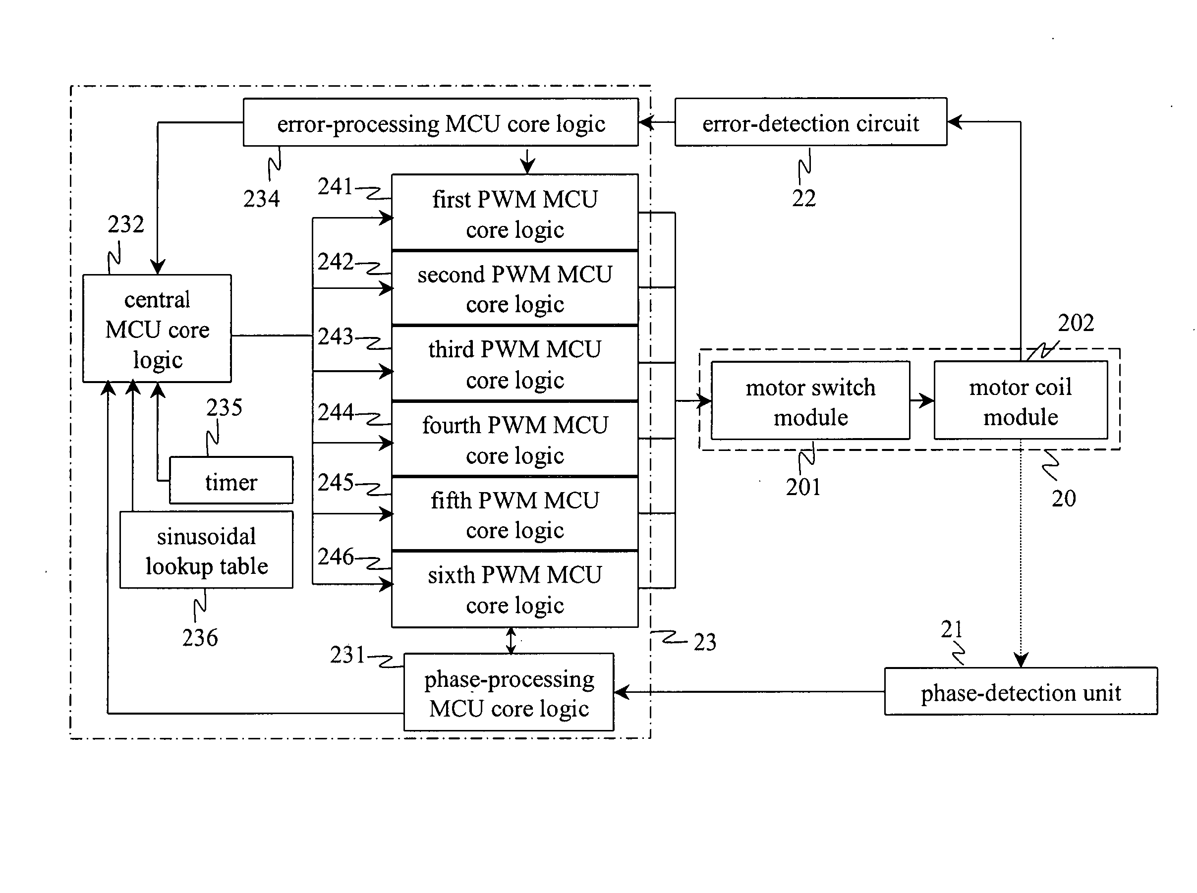
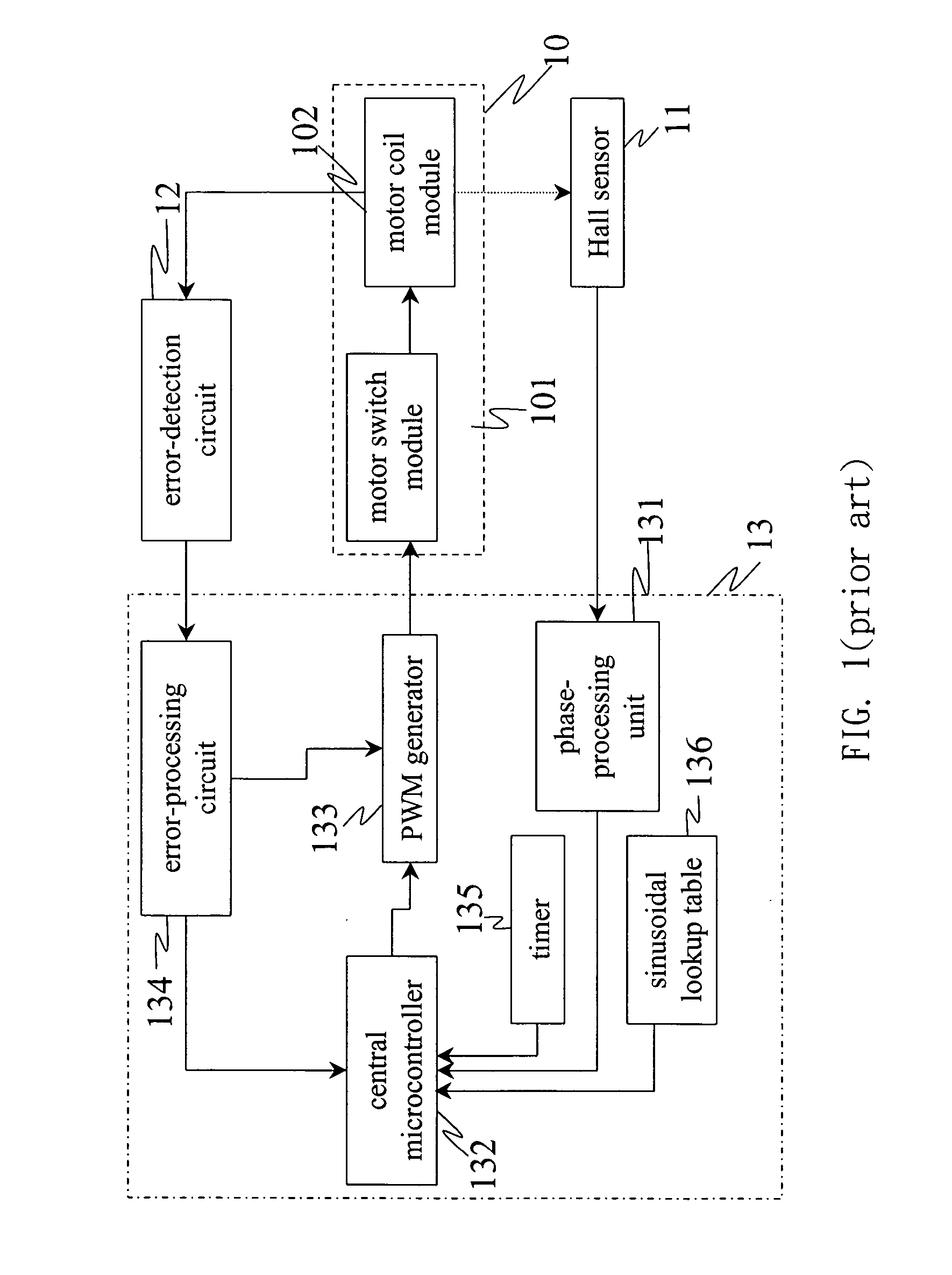
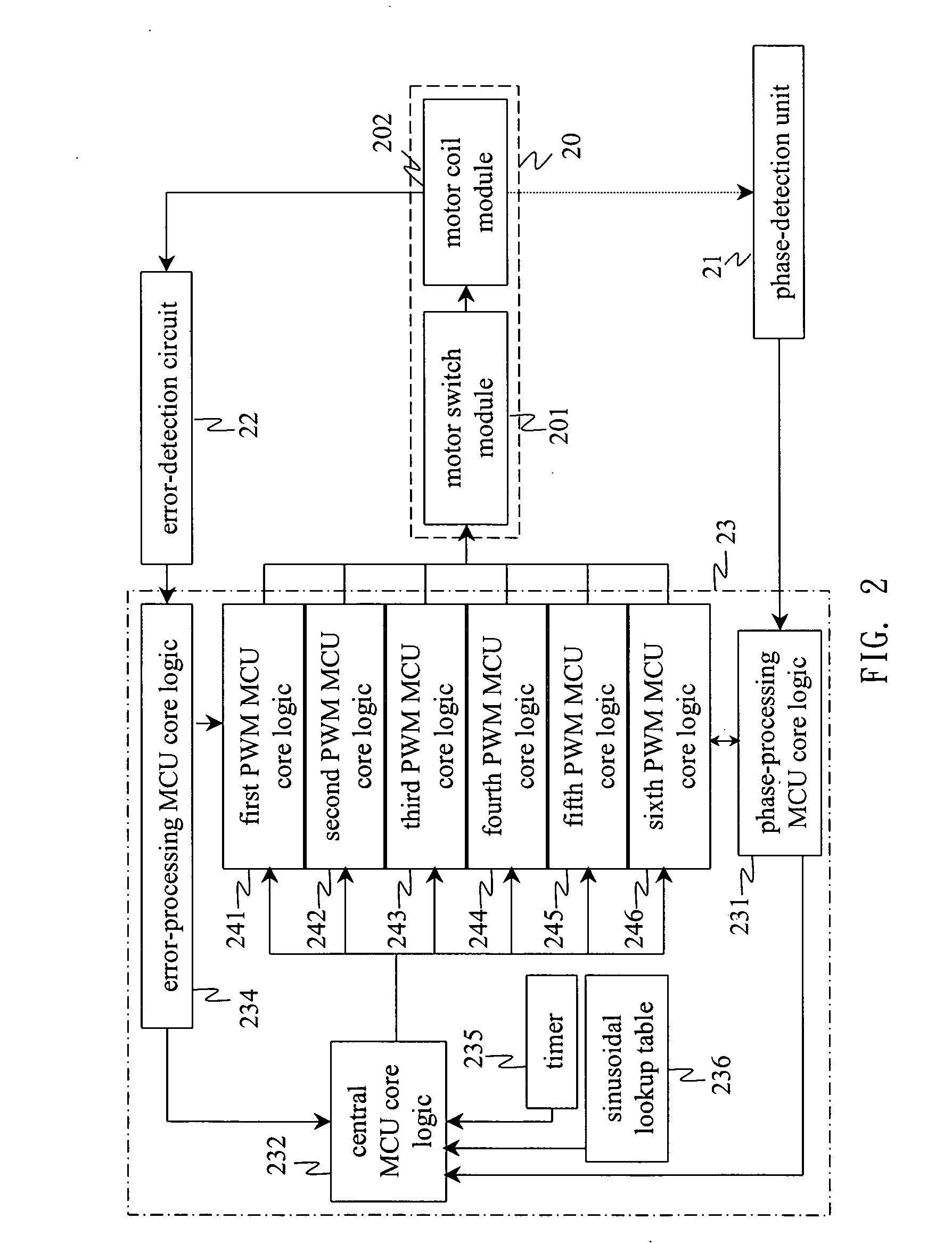
[0020] Motors are one of the most important electromechanical devices in industry automation. In order to achieve the optimal performance, the speed and position of a motor should be precisely and efficiently controlled with instant dynamic response. To meet the abovementioned requirements, the present invention proposes a real-time responsive motor control system, which replaces the conventional design wherein only one single MCU is used to control related PWM hardware by an MMCU (Multi-MicroController Unit) system with dedicated PWM MCU core logics, and utilizes a flexible software design to generate PWM signals for motor control. Thus, critical motor parameters can be controlled through software, which creates a new territory for future development.

[0021] Referring to FIG. 2, which is a block diagram schematically showing an embodiment of the motor control system according to the present invention, the motor control system of the present invention comprises: a motor device 20, a...


PUM


Abstract

The present invention discloses a real-time responsive motor control system comprising a central MCU (Microcontroller Unit) core logic and at least one PWM (Pulse Width Modulation) MCU core logic. The central MCU core logic takes care of all interrupt events. The PWM (Pulse Width Modulation) MCU core logic is dedicated to the transformation of PWM signals so that the PWM signals output to a motor device are highly accurate. Further, the central MCU core logic may directly control the PWM MCU core logics so that the switching timing of the PWM signals is even more accurate. The present invention provides a modularized hardware architecture with flexible software control. The system design is simple and the associated cost is reduced.

Description

BACKGROUND OF THE INVENTION [0001] 1. Field of the Invention [0002] The present invention relates to a motor control system, particularly to a real-time responsive motor control system. [0003] 2. Description of the Related Art [0004] Electromechanical control technology plays an important role in daily living; it facilitates rotary and linear motions required for applications ranging from less-sophisticated household appliances to sophisticated electronic systems and computers. With the increase in the scale and the complexity of electromechanical systems, more sophisticated electromechanical control technology is desired to meet the performance, safety and power efficiency requirements. Small-size electromechanical systems are usually employed in applications, which require highly precise electromechanical control. Large-size electromechanical systems, such as a robot, are usually employed in applications, which require very complex electromechanical control in which real-time resp...

Claims


Application Information

Patent Timeline
Patent Type & Authority Applications(United States)
IPC IPC(8): H02P7/29
CPCH02P6/001H02P6/34
Inventor LING, CHUAN-POCHANG, JUNG-LINLIN, SHIH-YU
Owner PADAUK TECH
Why Eureka
Try Eureka