Apparatus for an automotive data control, acquisition and transfer system

Inactive Publication Date: 2007-10-25
SYN TECH SYST
View PDF34 Cites 30 Cited by
  • Summary
  • Abstract
  • Description
  • Claims
  • Application Information

AI Technical Summary

Benefits of technology

[0041] It is yet another feature of the invention to provide an AIM that is equipped with a powerfail data save capability. Via this capability and the accompanying circuitry, the AIM is able to detect an impending powerfail and then store data, such as active operating instructions and in process data, to non-volatile memory before power is lost so that the data and operation associated therewith may be continued when power is restored. The active operating instructions and in process data include: current odometer and/or chronometers data, speed sensor pulse count, and any firmware update progresses. Further, the AIM's powerfail data save capability provides many benefits. For example, the AIM may be removed from the vehicle at any time. Also, no data, such as odometer and chronometer data, is ever lost, and the AIM is able to retain data during low voltage conditions which may occur during normal operation, such as during starting of the vehicle. In addition, no internal battery is required.
[0042] It is yet another feature of the present invention to provide an AIM's “smart on-board microprocessor/microcontroller” that is capable of communications with and receiving data from a global positioning system (GPS) receiver. Additionally, upon receipt of the GPS data, the AIM's “smart on-board microprocessor/microcontroller” is then able to process the data into vehicle tracking information, such as a maximum vehicle speed and where the speed occurred, a longest period of time when the vehicle was at rest both with and without the motor running and where the period of time occurred, etc.
[0043] It is yet another feature of the present invention to provide a system with AIMs having means for AIM to AIM direct communication. Direct AIM to AIM communication provides an autonomous method of retrieving information from AIM equipped vehicles that do not regularly drive within range of an FMU, such as road service vehicles, including tractors for roadside mowi

Problems solved by technology

The one common disadvantage of most of the systems is the inability to automatically positively identify a vehicle being fueled.
Further, with regard to systems that require some operator input, the operator input can produce fuel control and accounting errors.
While the inductive coil antennae pair has reduced the chance of operator error, the antennae pair has generated a major disadvantage in the process.
This response characteristic dictates that a secondary source of information is required in order to ascertain with which vehicle a long-range RF/ID tags is associated, which presents a major drawback to these fueling systems.
Further, systems having an onboard diagnostic bus (“OBD bus”) suffer from drawbacks.
This usually occurs only after the vehicle has problems, and consequently preventative maintenance becomes difficult.
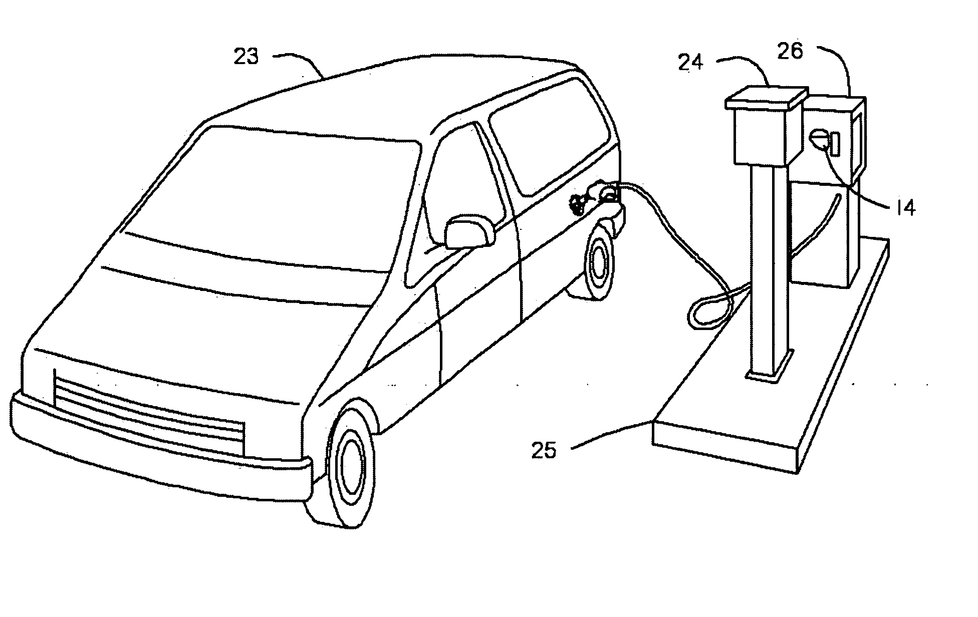
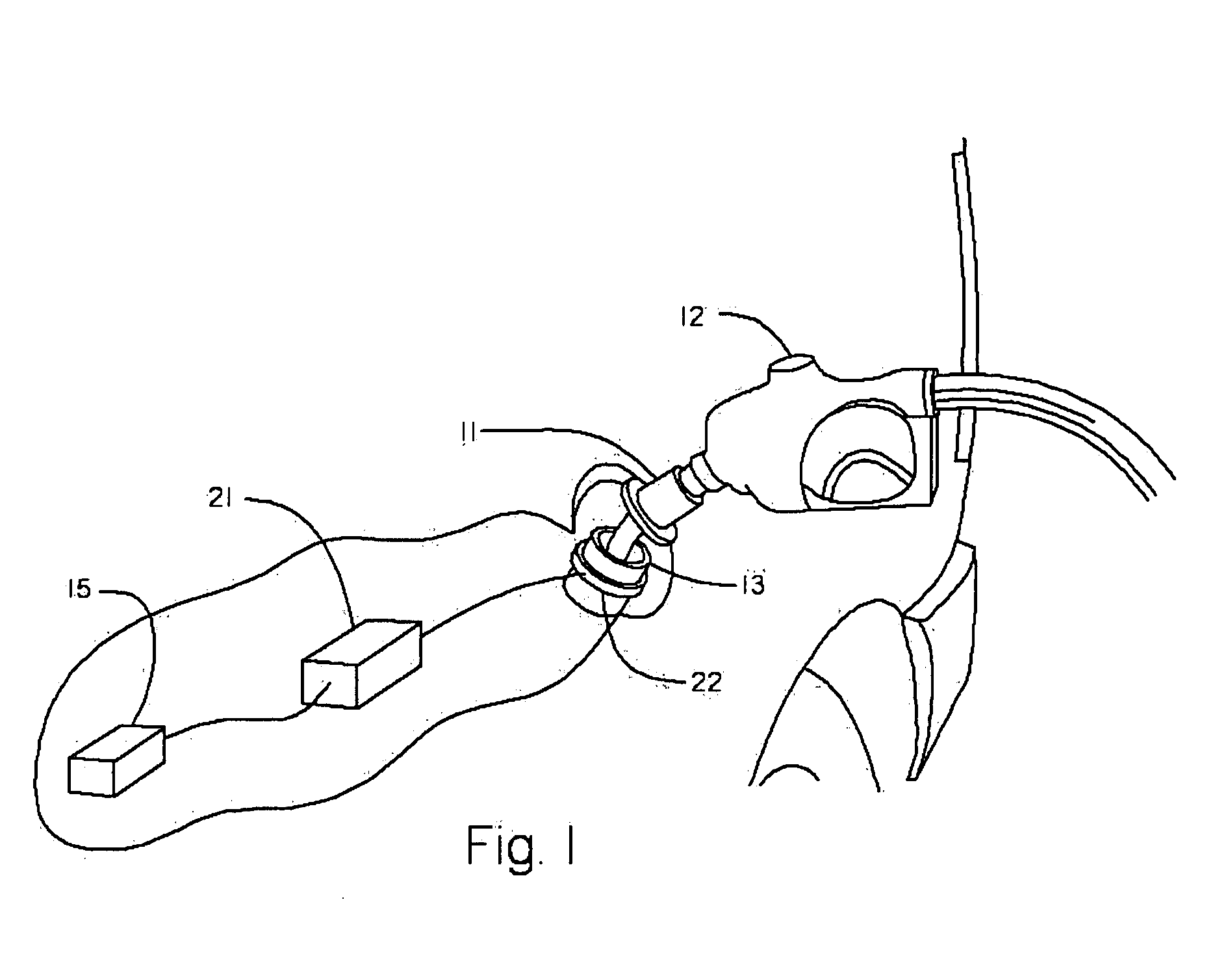
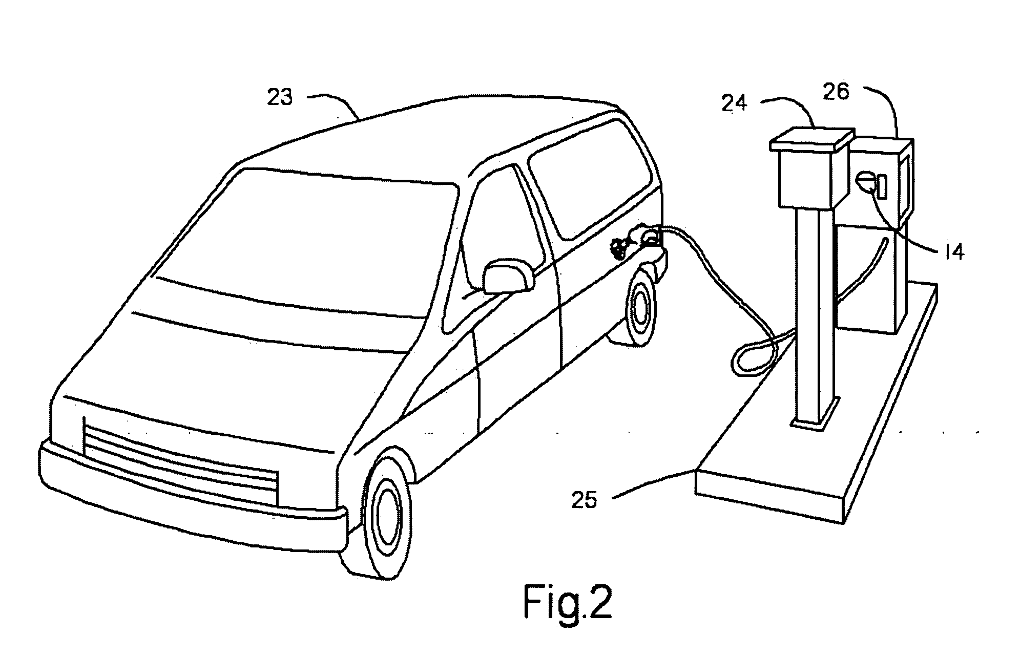
However, this system provides no positive assurance that the dispenser's fuel nozzle is actually installed in the vehicle to which the fuel control transmitter is affixed.
However, the system's non-powered RF/ID tag lacks the capability to directly monitor and accrue the vehicle's mileage.
For the second device to be capable of RF communications with a remote location, further power would be required from this second device and this further burdens the technical feasibility of meeting the intrinsic safety driven power limitations of the second device.
However, the

Method used


Image

  • Apparatus for an automotive data control, acquisition and transfer system
  • Apparatus for an automotive data control, acquisition and transfer system
  • Apparatus for an automotive data control, acquisition and transfer system

Examples


Embodiment Construction

[0057] Referring to FIGS. 1 and 2, the automotive data control, acquisition and transfer system of the present invention comprises an RF / ID tag 11 which is preferably molded into a splash guard of a liquid fuel nozzle 12, and a microcontroller-based automotive information module (“AIM”) 21 mounted within a vehicle 23. The AIM 21 includes an associated loop antenna 22 which is preferably mounted around fuel filler neck 13, an associated onboard diagnostic bus (“OBD bus”), and an OBD bus connector 15. “OBD bus” is used to refer to any of federal and industry diagnostic bus standards, including the OBD II, J1708 and J1939 bus standards. The system also comprises a fuel management unit (“FMU”) 24, which is preferably mounted on fuel island 25 having fuel dispenser 26 with a reset handle 14. Alternatively, the fuel island 25 can include a plurality of fuel dispensers with a plurality of fuel hoses per fuel dispenser provided at a fuel supply source.

[0058] The system further comprises a ...


PUM


Abstract

A system that controls, authorizes, and accounts fuel dispensed from fuel dispensers without the need for control and authorization input from individuals performing the fueling. The system comprises a radio frequency identification tag mounted on a fuel nozzle, an automotive information module mounted in the vehicle, a fuel island-mounted fuel management unit, and on-site or remotely-located software. The automotive information module interfaces with the vehicle's on-board computer system, the radio frequency identification tag, and the fuel management unit. With these interfaces, the automotive information module allows for autonomous creation and transfer of data and operational commands with in the disclosed system. The fuel management unit interfaces with the automotive information module, the fuel dispensers, and the software. With these interfaces, the fuel island-mounted fuel management unit provides autonomous fuel data processing. The software provides system owners, operators, and users raw data, analyzed data, and reports based on accumulated data from both the automotive information module and the fuel management unit.

Description

CROSS-REFERENCE TO RELATED APPLICATIONS [0001] This application claims priority to U.S. provisional application No. 60 / 791,218, which was filed on Apr. 12, 2006, and entitled “Apparatus for an Automotive Data Control, Acquisition and Transfer System,” the subject matter of which is hereby incorporated by reference in its entirety.BACKGROUND OF THE INVENTION [0002] 1. Field of the Invention [0003] The present invention is generally directed to fuel dispensing and autonomous automotive data collection and processing. Mores specifically, the present invention relates to the integration of a fuel dispensing and control system and autonomous automotive data collection into a single system that is suitable for both controlling, authorizing, and accounting fuel dispensed from fuel dispensers without requiring control and authorization input from individuals performing the fueling and for autonomous collection of automotive data. [0004] 2. Brief Discussion of the Related Art [0005] Solid st...

Claims


Application Information

Patent Timeline
IPC IPC(8): G05B19/00H04Q5/22B67D5/06G08B13/14G06F17/00B67D7/06
CPCG06Q20/367B67D7/348
Inventor LEIGH, CHRISTOPHERCHERNOSKY, MATTHEWGLENN, HERMANHOWARD, WILLIAMPOLLOCK, STEPHEN
Owner SYN TECH SYST
Why Eureka
Try Eureka