Combined egr cooler and plasma reactor

a plasma reactor and cooler technology, which is applied in the field of exhaust gas systems of internal combustion engines, can solve the problems of reducing the amount of exhaust gas which can be reintroduced into the engine, affecting the efficiency of combustion engines, so as to reduce the emissions of nitrogen oxides

Inactive Publication Date: 2007-11-22
DANA CANADA CORP
View PDF34 Cites 16 Cited by
  • Summary
  • Abstract
  • Description
  • Claims
  • Application Information

AI Technical Summary

Benefits of technology

[0009]According to another aspect, there is provided a method for reducing emissions of nitrogen oxides in the exhaust stream of an internal combustion engine. The method comprises: (a) providing a heat exchanger according to the invention in the exhaust stream of the internal combustion engine; (b) passing hot exhaust gases through the exhaust gas stream and through the second fluid passageway of the heat exchanger, such that hot exhaust gases flowing through the exhaust gas stream enter the heat exchanger through the second inlet port, flow through the second fluid passageway and exit the heat exchanger through the second outlet port; wherein the hot exhaust gases contain amounts of nitric oxide and carbonaceous soot; (c) passing a coolant through the first fluid passageway; and (d) energizing the voltage source so as to apply a voltage to the at least one electrode; wherein the voltage is of sufficient magnitude to cause the at least one electrode to generate a non-thermal plasma in the second fluid passageway, wherein the non-thermal plasma causes at least a portion of the nitric oxide in the hot exhaust gases to be converted to nitrogen dioxide, which reacts with the soot to generate carbon dioxide and nitrogen.

Problems solved by technology

Soot particulates in the air contribute to poor visibility and respiratory disease.
There are, however, limits on the amount of exhaust gas which can be reintroduced into the engine before power output and fuel economy are adversely impacted, and it has been found that the reintroduction of exhaust gases into the engine can significantly increase the soot content of the exhaust gas.
The presence of large amounts of soot in the exhaust gas can lead to fouling of the internal surfaces of the EGR cooler.
It is believed that fouling decreases the performance of the EGR cooler by creating a low conductivity thermal barrier on the heat exchange surfaces, by causing surface roughness on the heat exchange surfaces which increases the pressure drop, and by constricting the passages through which the exhaust gases flow, especially in small diameter tubes.
However, these systems suffer from the disadvantage that an additional component is required in the exhaust gas stream for the purpose of reducing soot content.
This adds to the cost and complexity of the exhaust system.

Method used


Image

  • Combined egr cooler and plasma reactor
  • Combined egr cooler and plasma reactor
  • Combined egr cooler and plasma reactor

Examples


Embodiment Construction

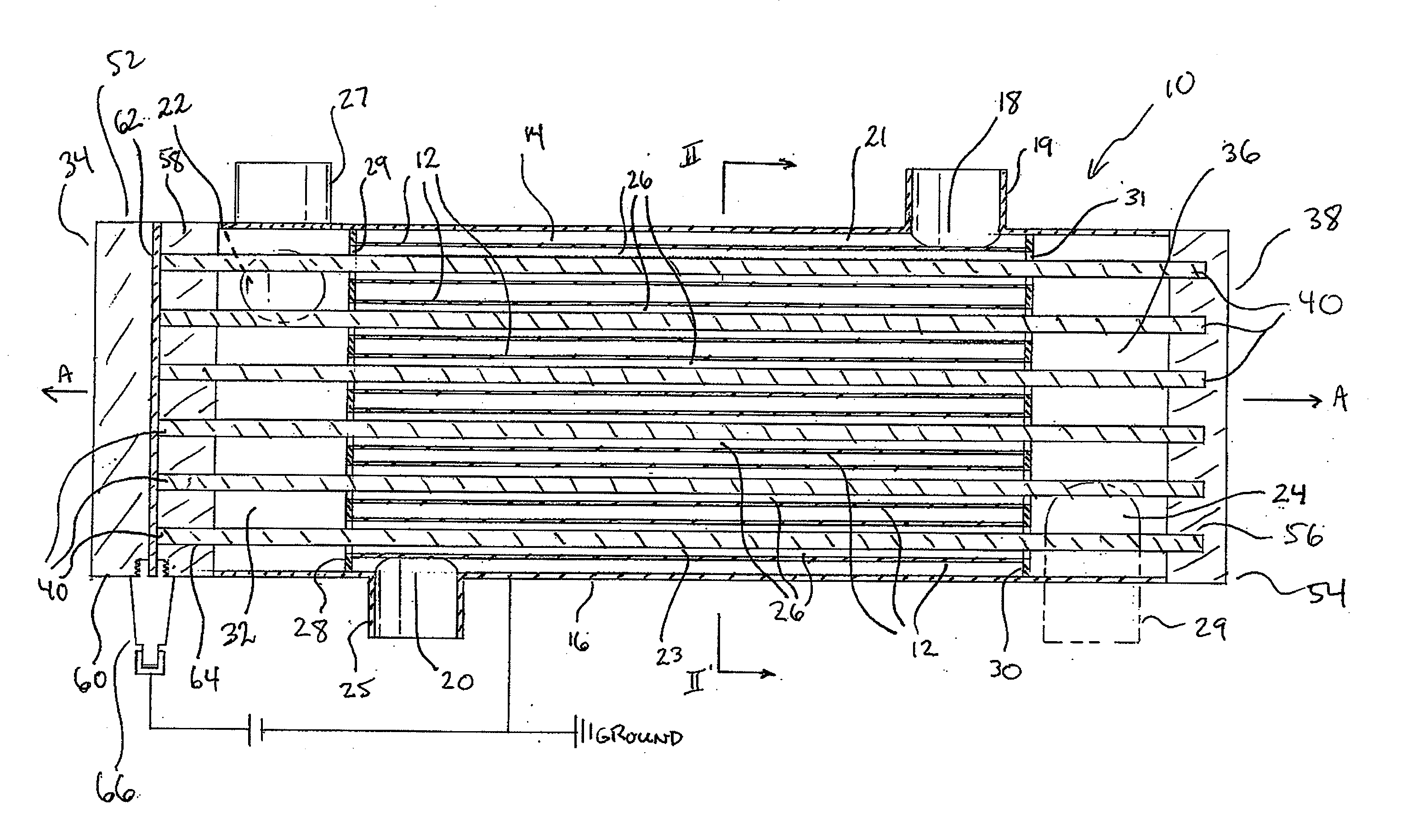
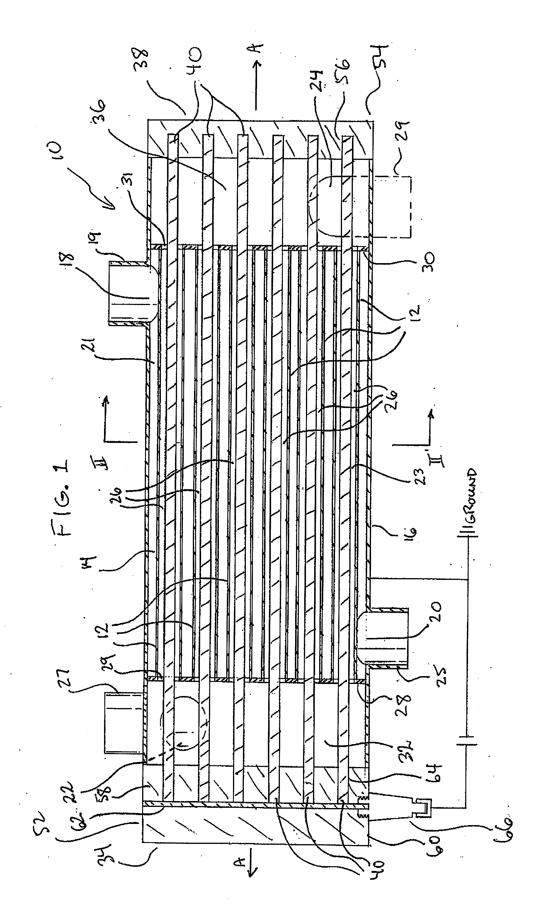
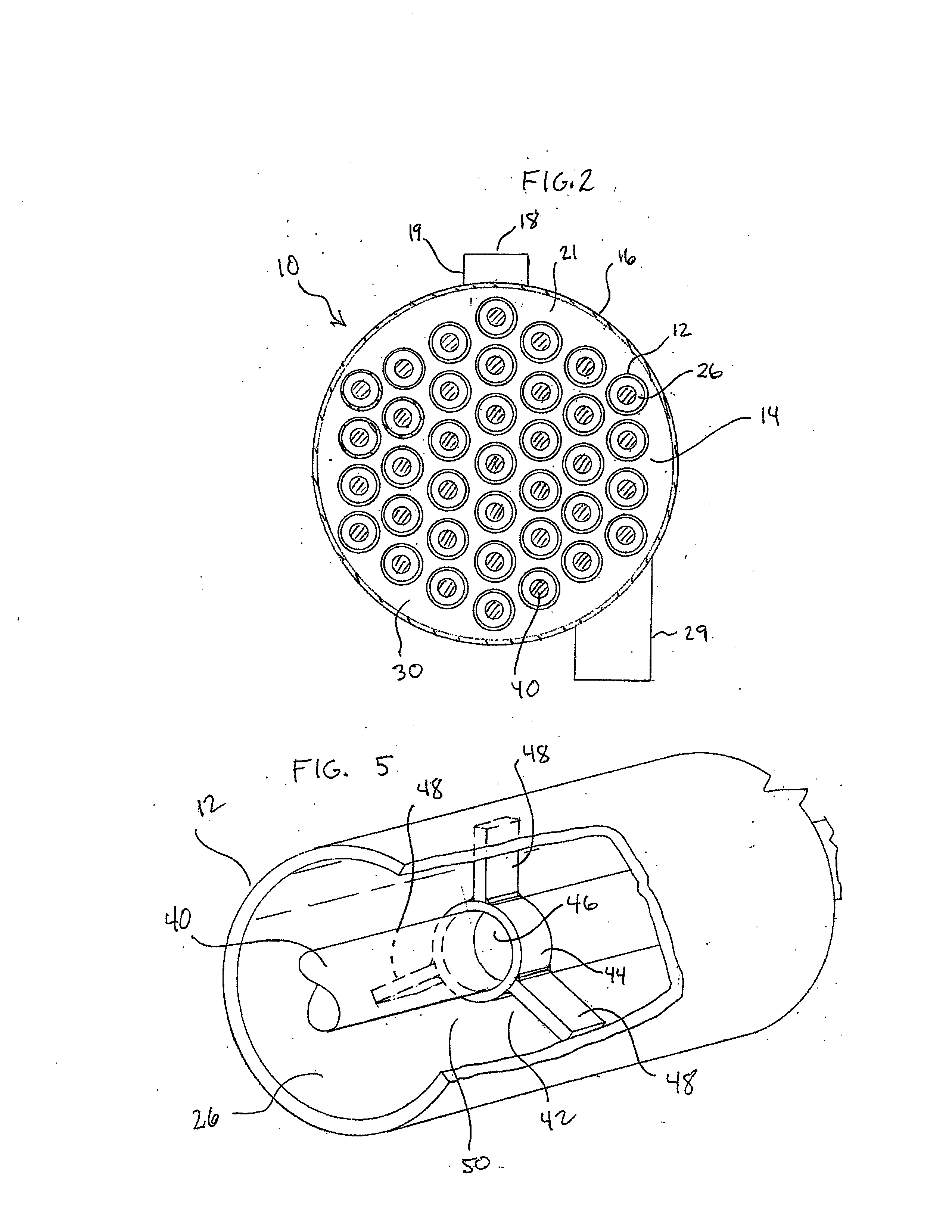
[0018]FIGS. 1 to 4 schematically illustrate a first preferred heat exchanger 10 according to the invention. Heat exchanger 10 is of the “shell and tube” type, comprising a plurality of tubes 12 extending parallel to one another and defining a longitudinal axis A. The tubes 12 are arranged in the form of a tube bundle 14. For simplicity, only six tubes 12 of tube bundle 14 are shown in FIG. 1. The tube bundle 14 is enclosed along its sides by an axially extending outer shell or housing 16. The housing 16 of heat exchanger 10 has a cylindrical side wall extending parallel to longitudinal axis A. It will be appreciated that the housing 16 is not necessarily cylindrical, but can be of any desired shape. For example, housing 16 may have a transverse cross section which is in the form of a regular or irregular polygon.

[0019]The side wall of housing 16 is provided with a first inlet port 18 and a first outlet port 20 which are in communication with one another through a first fluid passage...


PUM


Abstract

A combined EGR cooler and non-thermal plasma device has first and second fluid passageways which are in heat exchange communication with one another. One or more electrodes are located in the second fluid passageway. The electrodes are connected to a voltage source. When a voltage of sufficient magnitude is applied to the electrodes, a non-thermal plasma is generated in the second fluid passageway. The device can be constructed in the form of a shell-and-tube heat exchanger or a stacked-tube type heat exchanger, wherein the electrodes extend through the heat exchange tubes. Hot exhaust gases preferably flow through the tubes in heat exchange contact with a liquid coolant, thereby cooling the exhaust gases. The electrodes generate non-thermal plasma inside the tubes, converting at least a portion of the NO in the exhaust to NO2, which reacts with soot in the exhaust gases to generate CO2 and N2, thereby cleaning the exhaust gases.

Description

FIELD OF THE INVENTION[0001]The invention relates to exhaust gas systems of internal combustion engines which use exhaust gas recirculation (EGR) to reduce emissions of nitrogen oxides (NOx), and more specifically to such exhaust systems which also include means for reducing the soot content of the exhaust gas stream.BACKGROUND OF THE INVENTION[0002]The exhaust gases of internal combustion engines may contain a number of combustion by-products, including NOx, particulate matter such as carbonaceous soot, and unburned hydrocarbon fuel. In particular, the exhaust gases of diesel engines contain significant amounts of NOx and soot, and NOx content is also high in the exhaust gases of so-called “lean burn” engines in which the fuel is combusted with excess oxygen in order to increase engine efficiency. The exhaust gas streams of lean burn engines may also contain significant amounts of oxygen.[0003]The harmful effects of releasing NOx, soot and volatile organic compounds into the atmosp...

Claims


Application Information

Patent Timeline
Patent Type & Authority Applications(United States)
IPC IPC(8): F01N3/00
CPCF01N3/01F01N3/02F01N2240/02Y02T10/20F28D7/16F28D9/0043F28D21/0003F01N2240/28F28F2250/104Y02T10/12Y10S165/034F01N3/08F28D7/10F28F9/00F28F9/013F28F9/02
Inventor COTTON, JAMES SCOTT
Owner DANA CANADA CORP
Why Eureka
Try Eureka