Coupling arrangment

a technology of coupling arrangement and coupling shaft, which is applied in the direction of mechanical actuated clutches, electric devices, transportation and packaging, etc., can solve the problems of reduced flow resistance losses and complex route along which the medium flows, and achieves efficient cooling, high torque, and simple design

Inactive Publication Date: 2007-11-22
ZF FRIEDRICHSHAFEN AG
View PDF6 Cites 16 Cited by
  • Summary
  • Abstract
  • Description
  • Claims
  • Application Information

AI Technical Summary

Benefits of technology

[0007]The invention is based on the task of designing a coupling arrangement of this type in such a way that, even though it is provided with co

Problems solved by technology

In addition, both the complexity of the route along which the med

Method used


Image

  • Coupling arrangment
  • Coupling arrangment
  • Coupling arrangment

Examples


Embodiment Construction

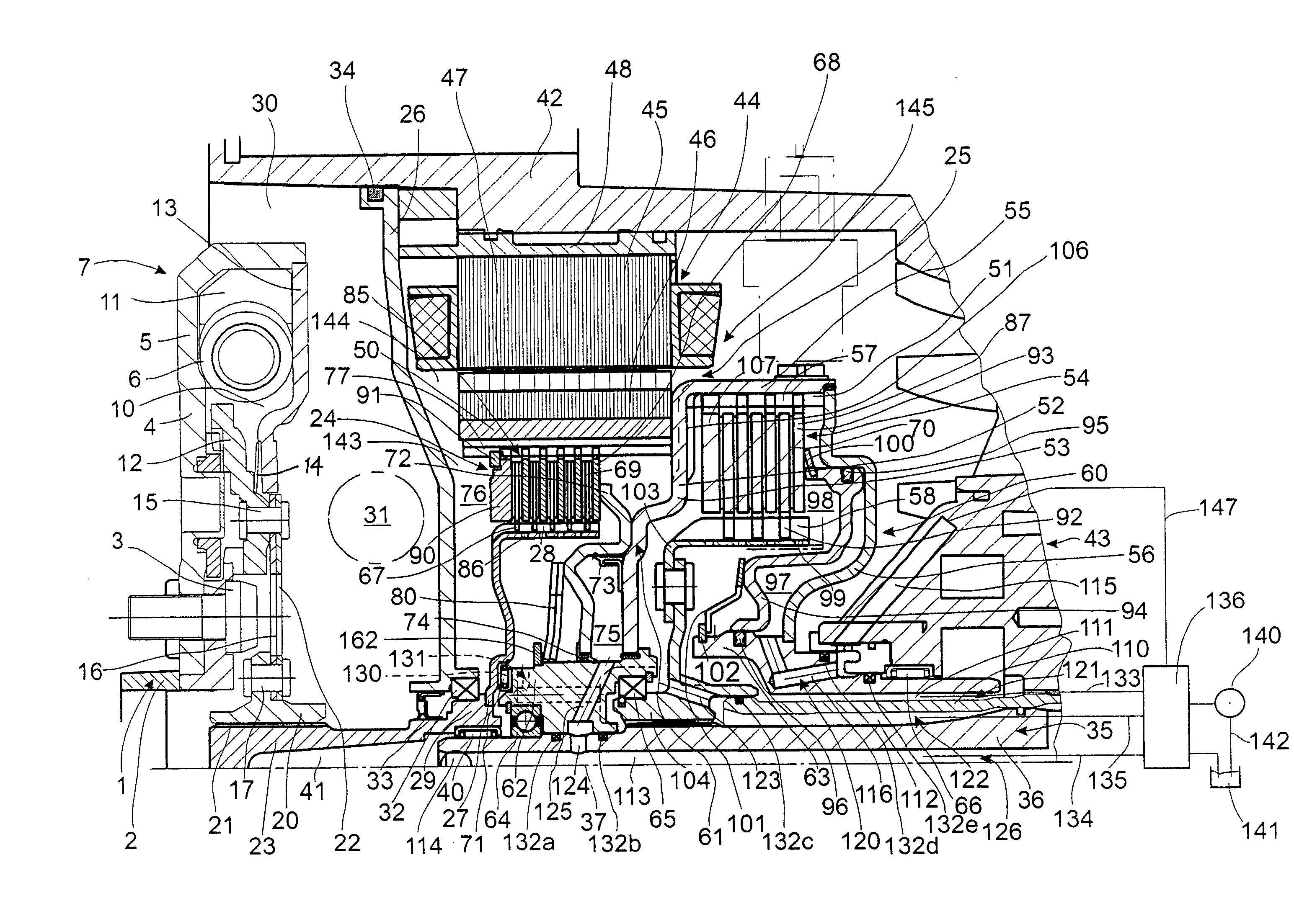
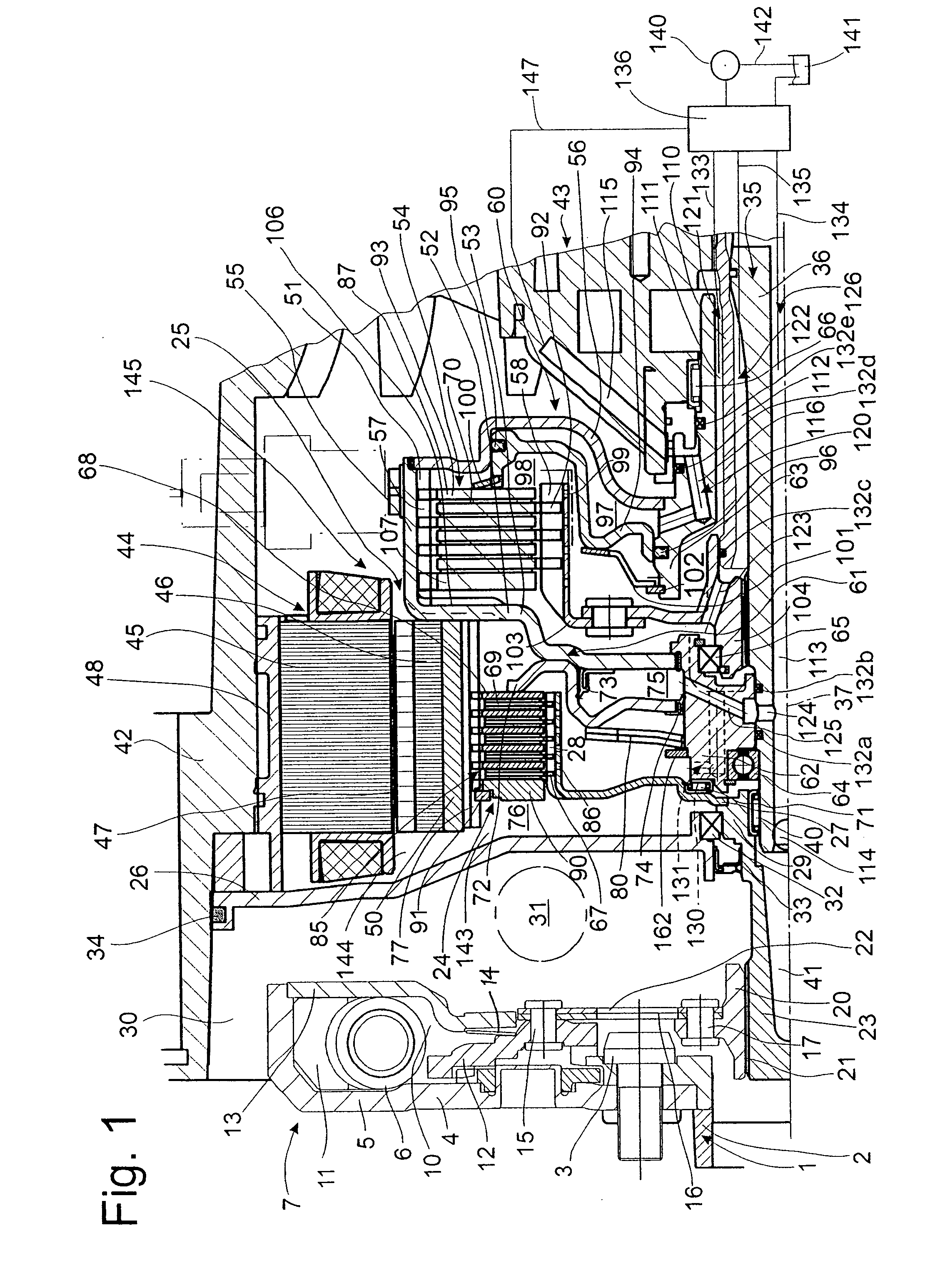
[0024]FIG. 1 shows in schematic fashion a crankshaft 2 of an internal combustion engine 1, to which a primary flange 4 of a torsional vibration damper 7 is connected by fastening elements 3. A cover plate 13 is attached to the radially outer area of the primary flange 4. This cover plate and the primary flange 4 together form the boundaries of a grease chamber 10, which serves to hold an energy storage set 6 acting in the circumferential direction, which is supported radially and possibly also circumferentially by slide elements 11. The energy storage set 6 is driven by the primary flange 4 and / or the cover plate 13 upon the introduction of torsional vibrations at the crankshaft 2, and at the other end, it is supported against a hub disk 12. The radially inner area of this hub disk 12 serves to hold axially elastic elements 16 by means of first connecting means 15. The axially elastic elements 16 for their own part carry a torsion damper hub 20 by means of second connecting means 17...


PUM


Abstract

A coupling arrangement includes a first clutch device for establishing a working connection between an electric machine and an internal combustion engine and a second clutch device for establishing a working connection between at least one of the machines and a takeoff. Each of the two clutch devices has its own clutch components in the form of at least one piston and a predetermined number of clutch elements. By means of the piston in question, a pressure space is at least essentially sealed off from a cooling space, which holds the clutch elements. Each of the pressure spaces of the two clutch devices has its own supply line, whereas only one of the cooling spaces of the two clutch devices has its own supply line, the cooling space of the other clutch device being connected by a line leading to the cooling space of the first-mentioned clutch device.

Description

BACKGROUND OF THE INVENTION[0001]1. Field of the Invention[0002]The invention pertains to a coupling arrangement for connecting an internal combustion engine to at least one of an electric machine and a takeoff, the arrangement including a first clutch having first clutch components for establishing a working connection between the engine and the electric machine, a second clutch having second clutch components for establishing a working connection between the takeoff and at least one of the engine and the electric machine, and a fluid supply source connected to at least one of the clutches by at least one fluid supply line.[0003]2. Description of the Related Art[0004]A coupling arrangement of this type is known from U.S. Pat. No. 6,668,953. This coupling arrangement has a first clutch device for establishing a working connection between an electric machine and an internal combustion engine when certain clutch components are in an engaged position and for separating the two machines...

Claims


Application Information

Patent Timeline
IPC IPC(8): F16D25/10F16D13/72
CPCB60K6/387B60K6/48F16D25/10Y02T10/6221F16H57/0473F16H57/0476F16D25/123B60L3/0061B60L2240/425B60L2240/445B60L2220/50B60L50/16Y02T10/62Y02T10/64Y02T10/7072F16D25/0638F16D21/06Y02T10/70
Inventor SUDAU, JORGFENN, PETERLOTZE, RUDIGER
Owner ZF FRIEDRICHSHAFEN AG
Why Eureka
Try Eureka