
Lung reduction system

a technology of a reduction system and a lungs, applied in the field of systems and methods, can solve the problems of large amount of oxygen, increased annual cost of oxygen therapy, soreness and irritation of the nose, etc., and achieve the effect of increasing the expiratory flow

Inactive Publication Date: 2007-11-22
PORTAERO
View PDF99 Cites 3 Cited by
  • Summary
  • Abstract
  • Description
  • Claims
  • Application Information

AI Technical Summary

Benefits of technology

[0016] The present invention overcomes the disadvantages associated with treating chronic obstructive pulmonary disease, as briefly described above, by utilizing the phenomenon of collateral ventilation to increase the expiratory flow from a diseased lung. The present invention also provides a means for assisting in or facilitating pulmonary decompression to compress the diseased area or area of the lung or lungs to a smaller volume.
[0019] In accordance with a third aspect, the present invention is directed to a method for reducing the volume of a hyperinflated portion of a lung of a patient. The device comprising determining a site of hyperinflation in a patient's lung, and allowing air from the hyperinflated portion of the lung to vent through a device to the ambient environment and preventing air from the ambient environment from re-entering the lung through the device.
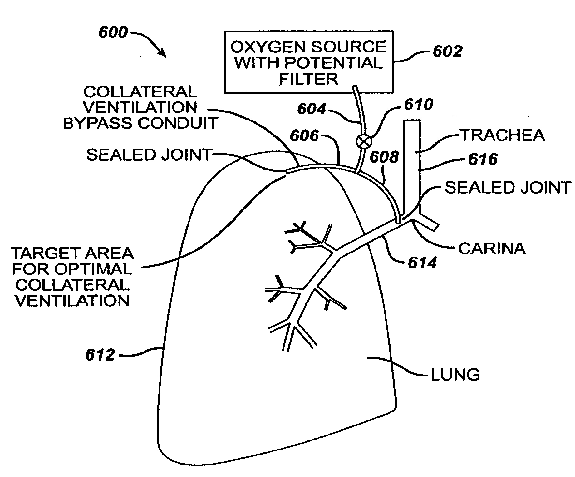
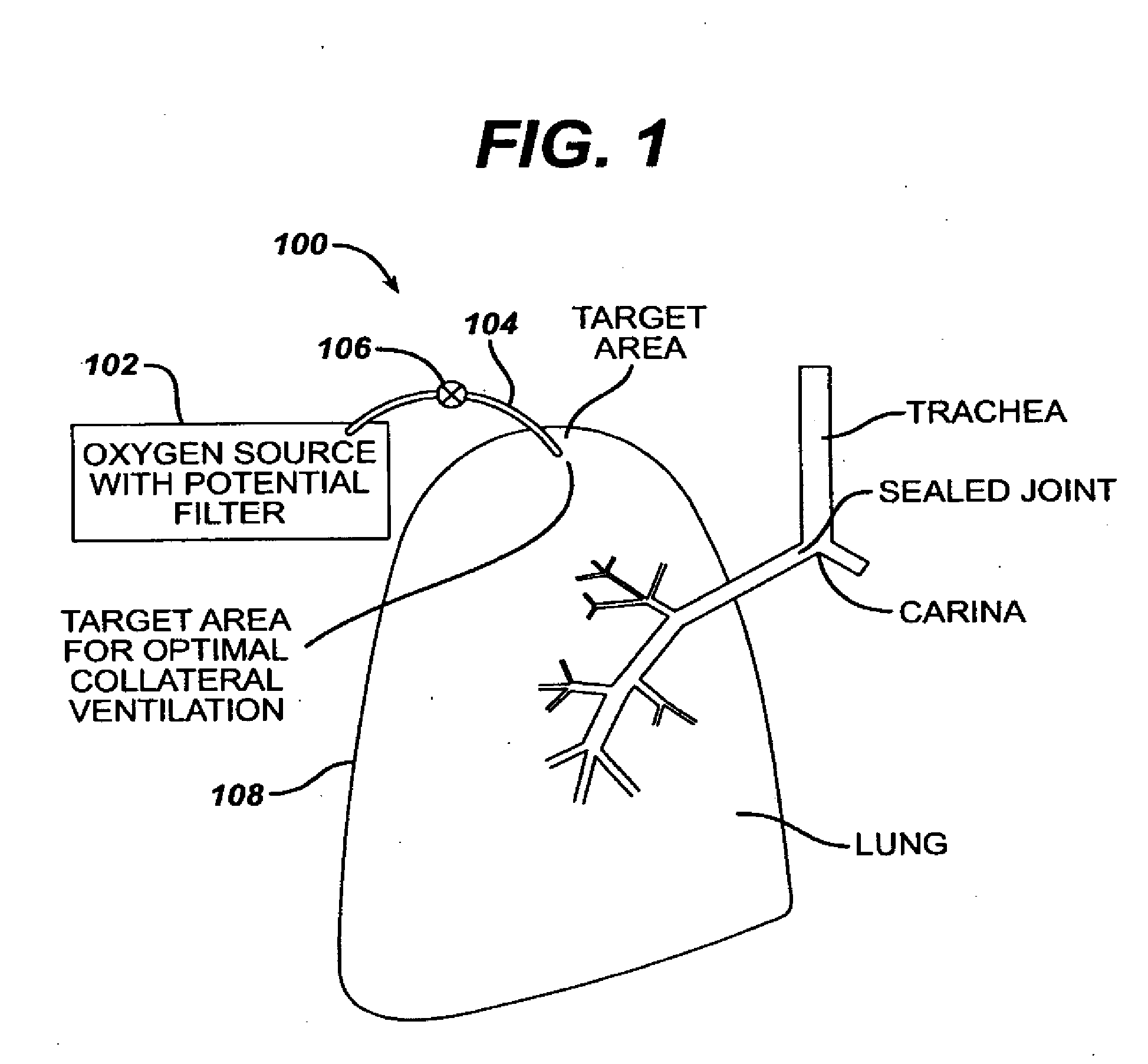
[0020] The long-term oxygen therapy system of the present invention delivers oxygen directly to diseased sites in a patient's lungs. Long term oxygen therapy is widely accepted as the standard treatment for hypoxia caused by chronic obstructive pulmonary disease, for example, pulmonary emphysema. Pulmonary emphysema is a chronic obstructive pulmonary disease wherein the alveoli of the lungs lose their elasticity and the walls between adjacent alveoli are destroyed. As more and more alveoli walls are lost, the air exchange surface area of the lungs is reduced until air exchange becomes seriously impaired. The combination of mucus hypersecretion and dynamic air compression is a mechanism of airflow limitation in chronic obstructive pulmonary disease. Dynamic air compression results from the loss of tethering forces exerted on the airway due to the reduction in lung tissue elasticity. Essentially, stale air accumulates in the lungs, thereby depriving the individual of oxygen. Various methods may be utilized to determine the location or locations of the diseased tissue, for example, computerized axial tomography or CAT scans, magnetic resonance imaging or MRI, positron emission tomograph or PET, and / or standard X-ray imaging. Once the location or locations of the diseased tissue are located, anastomotic openings are made in the thoracic cavity and lung or lungs and one or more oxygen carrying conduits are positioned and sealed therein. The one or more oxygen carrying conduits are connected to an oxygen source which supplies oxygen under elevated pressure directly to the diseased portion or portions of the lung or lungs. The pressurized oxygen essentially displaces the accumulated air and is thus more easily absorbed by the alveoli tissue. In addition, the long term oxygen therapy system may be configured in such a way as to provide collateral ventilation bypass in addition to direct oxygen therapy. In this configuration, an additional conduit may be connected between the main conduit and the individual's trachea with the appropriate valve arrangement. In this configuration, stale air may be removed through the trachea when the individual exhales since the trachea is directly linked with the diseased site or sites in the lung via the conduits.
[0021] The long term oxygen therapy system of the present invention improves oxygen transfer efficiency in the lungs thereby reducing oxygen supply requirements, which in turn reduces the patient's medical costs. The system also allows for improved self-image, improved mobility, greater exercise capability and is easily maintained.
[0025] The pulmonary decompression device of the present invention removes air from hyperinflated regions of the lung or lungs of a patient by creating a slight pressure differential between the internal volume of the lung and a location external of the lung. An apparatus such as a vacuum fan or pump creates the pressure differential, thereby removing the trapped air and reducing the volume of diseased tissue.
[0026] The lung reduction device of the present invention allows trapped air from hyperinflated regions of the lung or lungs of a patient to vent to the external environment through a one-way valve. The valve prevents air from flowing back into the lung or lungs.

Problems solved by technology

However, with the desire to contain medical costs, there is a growing concern that the additional cost of providing continuous oxygen therapy for chronic lung disease will create an excessive increase in the annual cost of oxygen therapy.
Such treatment, however, requires a large amount of oxygen, which is wasteful and can cause soreness and irritation to the nose, as well as being potentially aggravating.
Other undesirable effects have also been reported.
Such devices are generally intended only for use with a patient who is not breathing spontaneously and are not suitable for the long term treatment of chronic lung disease.
As previously described, the use of such tubes has been restricted medically to emergency situations where the patient would otherwise suffocate due to the blockage of the airway.
Such emergency tracheotomy tubes are not suitable for long term therapy after the airway blockage is removed.
Although tracheotomy tubes are satisfactory for their intended purpose, they are not intended for chronic usage by outpatients as a means for delivering supplemental oxygen to spontaneously breathing patients with chronic obstructive pulmonary disease.
The Jacobs catheter, like the other tracheotomy tubes previously used, is not suitable for long term outpatient use, and could not easily be adapted to such use.
It does not, however, lend itself to outpatient use and maintenance, such as periodic removal and cleaning, primarily because the connector between the catheter and the oxygen supply hose is adjacent and against the anterior portion of the trachea and cannot be easily seen and manipulated by the patient.
Furthermore, the catheter is not provided with positive means to protect against kinking or collapsing which would prevent its effective use on an outpatient basis.
Also, as structured, the oxygen can strike the carina, resulting in an undesirable tickling sensation and cough.
In addition, in such devices, if a substantial portion of the oxygen is directed against the back wall of the trachea causing erosion of the mucosa in this area which may cause chapping and bleeding.
Overall, because of the limited output from the device, it may not operate to supply sufficient supplemental oxygen when the patient is exercising or otherwise quite active or has severe disease.
This collapsing phenomenon also intensifies the inability for individuals to exhale completely.
Essentially, air is not effectively expelled and stale air accumulates in the lungs.
Bronchodilating drugs only work on a percentage of patients with chronic obstructive pulmonary disease and generally only provides short term relief.
Oxygen therapy is impractical for the reasons described above, and lung volume reduction surgery is an extremely traumatic procedure that involves removing part of the lung.

Method used


Image

  • Lung reduction system
  • Lung reduction system
  • Lung reduction system

Examples


Embodiment Construction

[0044] Air typically enters the mammalian body through the nostrils and flows into the nasal cavities. As the air passes through the nostrils and nasal cavities, it is filtered, moistened and raised or lowered to approximately body temperature. The back of the nasal cavities is continuous with the pharynx (throat region); therefore, air may reach the pharynx from the nasal cavities or from the mouth. Accordingly, if equipped, the mammal may breath through its nose or mouth. Generally air from the mouth is not as filtered or temperature regulated as air from the nostrils. The air in the pharynx flows from an opening in the floor of the pharynx and into the larynx (voice box). The epiglottis automatically closes off the larynx during swallowing so that solids and / or liquids enter the esophagus rather than the lower air passageways or airways. From the larynx, the air passes into the trachea, which divides into two branches, referred to as the bronchi. The bronchi are connected to the ...


PUM


Abstract

A long term oxygen therapy system having an oxygen supply directly linked with a patient's lung or lungs may be utilized to more efficiently treat hypoxia caused by chronic obstructive pulmonary disease such as emphysema and chronic bronchitis. The system includes an oxygen source, one or more valves and fluid carrying conduits. The fluid carrying conduits link the oxygen source to diseased sites within the patients lungs. A collateral ventilation bypass trap system directly linked with a patient's lung or lungs may be utilized to increase the expiratory flow from the diseased lung or lungs, thereby treating another aspect of chronic obstructive pulmonary disease. The system includes a trap, a filter / one-way valve and an air carrying conduit. In various embodiments, the system may be intrathoracic, extrathoracic or a combination thereof. A pulmonary decompression device may also be utilized to remove trapped air in the lung or lungs, thereby reducing the volume of diseased lung tissue. A lung reduction device may passively decompress the lung or lungs. In order for the system to be effective, an airtight seal between the parietal and visceral pleurae is required. Chemical pleurodesis is utilized for creating the seal.

Description

CROSS REFERENCE TO RELATED APPLICATIONS [0001] This application claims the benefit of Provisional Application No. 60 / 475,291 filed Jun. 3, 2003.BACKGROUND OF THE INVENTION [0002] 1. Field of the Invention [0003] The present invention relates to systems and methods for removing trapped air in emphysematous lungs, and more particularly, to systems and methods for removing trapped air in emphysematous hyperinflated lungs by bypassing non-patent airways via a conduit through the outer pleural layer of the lung to a containment / trap device. The present invention also relates to a collateral ventilation bypass system that utilizes the trachea for expelling trapped air rather than a containment / trap device. The present invention also relates to a device and methodology to assist in pulmonary decompression and non-surgical / resection lung volume reduction. The present invention also relates to systems and methods for chemical pleurodesis. [0004] 2. Discussion of the Related Art [0005] As a r...

Claims


Application Information

Patent Timeline
Patent Type & Authority Applications(United States)
IPC IPC(8): A61M16/00A61B17/00A61F2/04A61M1/00A61M16/04
CPCA61F2002/043A61M16/04A61M16/0406A61M2205/0244A61M2210/1039A61M39/0247A61M2202/0208A61M2202/03A61M16/101A61M16/106A61M2202/0007
Inventor TANAKA, DON
Owner PORTAERO
Learn More