Method and apparatus for hot swap of line replaceable modules for AC and DC electric power systems

a technology of electric power system and hot swap, which is applied in the direction of energy-saving board measures, coupling device connections, instruments, etc., can solve the problems of adversely affecting reliability, adversely affecting reliability, and affecting reliability, and achieves low resistance, low resistance, and high resistance to the module

Inactive Publication Date: 2007-11-22
HONEYWELL INT INC
View PDF32 Cites 24 Cited by
  • Summary
  • Abstract
  • Description
  • Claims
  • Application Information

AI Technical Summary

Benefits of technology

[0012]The present invention is directed to a method and an apparatus for hot swap of AC or DC line replaceable modules. According to a first aspect of the present invention, an apparatus for hot swap of AC or DC line replaceable modules comprises: a pin assembly, the pin assembly being connectable to a module and connectable to a backplane, the pin assembly resistively reducing a current associated with the module during disconnection of the module from the backplane, and presenting a high resistance to the module during connection of the module to the backplane, and a low resistance to the module at completion of the connection of the module to the backplane; and a hot swap detector connectable to the pin assembly, the hot swap detector detecting the disconnection of the module from the backplane, and detecting the connection of the module to the backplane.

Problems solved by technology

If not designed for properly, hot swap can cause severe electrical, mechanical, thermal and operational problems in an electrical system.
Pulling a board / module out while there is current passing through the module connectors, or inserting a board / module with all bulk / bypass capacitors at zero volts, can introduce severe electrical voltage / current transients which may adversely impact reliability and lead to safety consequences.
For example, current chopping introduces Ldi / dt variations (where L is inductance of a load, for example) leading to very large voltage transients which are a major safety concern for maintenance people, as large voltage transients can cause high voltage electrical shock.
Currently, due to excessive cost, weight and board space penalties, AC and DC SSPC LRM cards do not include additional circuit breakers or relays which could be turned-off before initiating a hot swap of a failed LRM with one or more SSPC devices failed short.
Hence, conventional hot swap is not properly designed for such LRM / boards.
Even though hot swap technologies have become an integral part of major operating systems in telecommunications, networking and other computer industries, such hot swap systems have not been utilized for high-voltage AC and DC electrical power systems in the aerospace industry or in industrial environments.
This technique, however, does not detect board / module insertion or extraction at the beginning of the hot swap process in order to prevent disturbances to various data lines.
This technique also does not communicate with the remaining software of the larger electrical system to prevent further abnormal operation or possible damage on circuits surrounding the modules / boards that are hot-swapped.
In this technique, however, two power supplies and a complex long / short pin system with partially insulated sleeves are needed, and the method is not cost effective.
Moreover, this method may cause short on the power supplies, particularly if the voltage levels of the power supplies are different.
This method may introduce significant electrical (current / voltage) transients during hot swap due to potential current chopping when pulling a module out of a backplane.

Method used


Image

  • Method and apparatus for hot swap of line replaceable modules for AC and DC electric power systems
  • Method and apparatus for hot swap of line replaceable modules for AC and DC electric power systems
  • Method and apparatus for hot swap of line replaceable modules for AC and DC electric power systems

Examples


Embodiment Construction

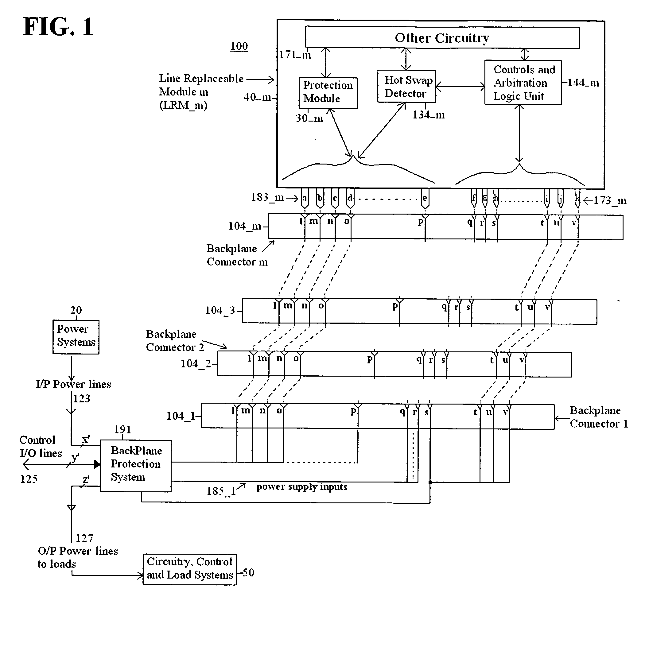
[0033]Aspects of the invention are more specifically set forth in the accompanying description with reference to the appended figures. FIG. 1 is a general functional block diagram of a subassembly electrical system containing line replaceable modules (LRMs) with hot-swap capability according to an embodiment of the present invention. The electrical system 100 illustrated in FIG. 1 includes the following components: power systems 20; m line replaceable modules (LRMs) 40_1, . . . , 40—m of which LRM 40—m is shown; circuitry, control and load systems 50; m backplane connectors 104_1, 104_2, . . . , 104—m; and a backplane protection system 191. Operation of the electrical system 100 in FIG. 1 will become apparent from the following discussion.

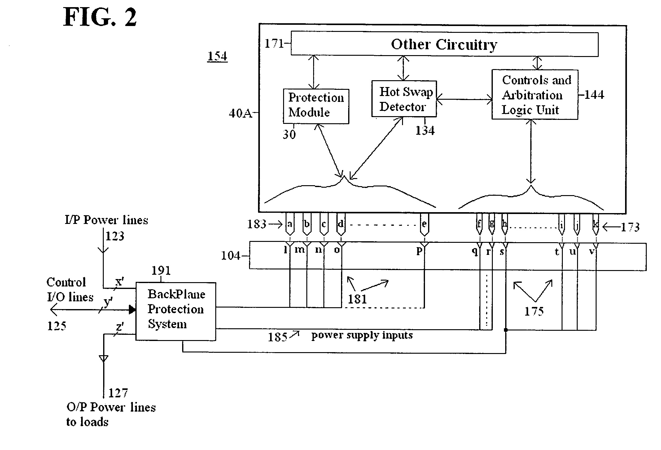
[0034]LRM 40—m includes a protection module 30—m; a hot swap detector 134—m; other circuitry 171—m; a controls and arbitration logic unit 144—m; and pin systems 183—m and 173—m. Backplane connector 104—m includes pin systems that connect / disconnect...


PUM


Abstract

A method and an apparatus are used in hot swap of AC or DC line replaceable modules (40A). The apparatus according to one embodiment comprises a pin assembly (183), the pin assembly (183) being connectable to a module (40A) and connectable to a backplane (104), the pin assembly (183) resistively reducing a current associated with the module (40A) during disconnection of the module (40A) from the backplane (104), and presenting a high resistance to the module (40A) during connection of the module (40A) to the backplane (104), and a low resistance to the module (40A) at completion of the connection of the module (40A) to the backplane (104); and a hot swap detector (134) connectable to the pin assembly (183), the hot swap detector (134) detecting the disconnection of the module (40A) from the backplane (104), and detecting the connection of the module (40A) to the backplane (104). In one embodiment, the method and apparatus provide a main advantage of preventing electrical arcs and damage to mating pins (183). Embodiments for the method and apparatus prevent any excessive voltage and / or current transients that would disturb the operation of other connected subsystems.

Description

CROSS REFERENCE TO RELATED APPLICATION[0001]This non-provisional application is related to co-pending non-provisional application titled “Method and Apparatus for Integrated Active-Diode-ORing and Soft Power Switching” filed concurrently herewith, the entire contents of which are hereby incorporated by reference.BACKGROUND OF THE INVENTION[0002]1. Field of the Invention[0003]The present invention relates to electric power systems, and more particularly to a method and apparatus for hot swap of modules for electric power systems.[0004]2. Description of the Related Art[0005]Electric systems used in complex environments such as aerospace systems, more electric aircraft systems, industrial environments, vehicles, etc., include a large number of electric modules. Various electric modules may need to be extracted and replaced with other electric modules, to change functionality or to replace electric modules that exhibit faults.[0006]Hot swap, hot-plug, and hot-dock are terms used interch...

Claims


Application Information

Patent Timeline
Patent Type & Authority Applications(United States)
IPC IPC(8): G06F13/00
CPCH02J1/10Y02T50/54Y02T50/545H02J4/00H02J2310/44H02J1/001Y02T50/50
Inventor KOJORI, HASSAN ALI
Owner HONEYWELL INT INC
Why Eureka
Try Eureka