
Ceramic Honeycomb Filter, Exhaust Gas-Cleaning Apparatus, and Exhaust Gas-Cleaning Method

Inactive Publication Date: 2007-12-06
HITACHI METALS LTD +1
View PDF6 Cites 8 Cited by
  • Summary
  • Abstract
  • Description
  • Claims
  • Application Information

AI Technical Summary

Benefits of technology

[0012] Accordingly, an object of the present invention is to provide a honeycomb filter regeneratable by continuously burning particulate matter in an exhaust gas by the action of a catalyst carried thereby, to surely prevent pressure loss increase by the accumulation of particulate matter in its pores and avoid the breakage of the filter, so that it can be used stably for a long period of time.
[0014] A further object of the present invention is to provide a method for cleaning an exhaust gas while preventing the clogging of a honeycomb filter and thus pressure loss increase without breakage of a honeycomb filter. DISCLOSURE OF THE INVENTION

Problems solved by technology

When the amount of particulate matter captured in pores reaches a predetermined level or more, the pores are clogged, resulting in increased pressure loss of the honeycomb filter and thus engine power decrease.
In the regeneration of the honeycomb filter, the more particulate matter is captured, the more difficult it is to uniformly control the temperature inside the honeycomb filter.
A honeycomb filter tends to be subjected to larger temperature elevation particularly in portions in which particulate matter is accumulated at a higher concentration, thus vulnerable to breakage by thermal stress generated by the burning of particulate matter.
In some cases, the temperature of a honeycomb filter is elevated to the melting temperature of a ceramic material or higher, causing meltdown in cell walls.
When the highest temperature of the honeycomb filter during regeneration is low enough to prevent breakage and meltdown, some particulate matter remains unburned, failing to sufficiently reduce the pressure loss of the honeycomb filter even after the regeneration treatment.
However, because the heating means is arranged only on the inlet side of the cells, it is difficult to uniformly control the temperature of a honeycomb filter long in a flow path direction from the inlet side to the outlet side.
When a large amount of particulate matter is captured, the heat generation of particulate matter locally elevates the temperature of a honeycomb filter, resulting in breakage and meltdown.
However, even this particulate filter for a diesel exhaust gas fails to prevent pressure loss increase by clogging with particulate matter in some cases.
This appears to be due to the fact that particularly when diesel cars are trapped in congestion in large cities, driving continues in a state where catalysts carried by filters are at temperatures lower than about 300° C., the lower limit of catalyst-activating temperatures, so that particulate matter is not sufficiently burned.
However, when a fuel supplied in an unburned state is not sufficiently reacted in this exhaust gas-cleaning method, the particulate matter cannot be fully burned, resulting in premature pressure loss increase by clogging with particulate matter, and thus failing to continue using the filter.
In this honeycomb filter, however, the exhaust gas temperature is elevated rapidly near the inlet-side plugs whenever the fuel is injected, so that the inlet-side plugs are likely to be broken when used for a long period of time.

Method used


Image

  • Ceramic Honeycomb Filter, Exhaust Gas-Cleaning Apparatus, and Exhaust Gas-Cleaning Method
  • Ceramic Honeycomb Filter, Exhaust Gas-Cleaning Apparatus, and Exhaust Gas-Cleaning Method
  • Ceramic Honeycomb Filter, Exhaust Gas-Cleaning Apparatus, and Exhaust Gas-Cleaning Method

Examples


examples 1-5

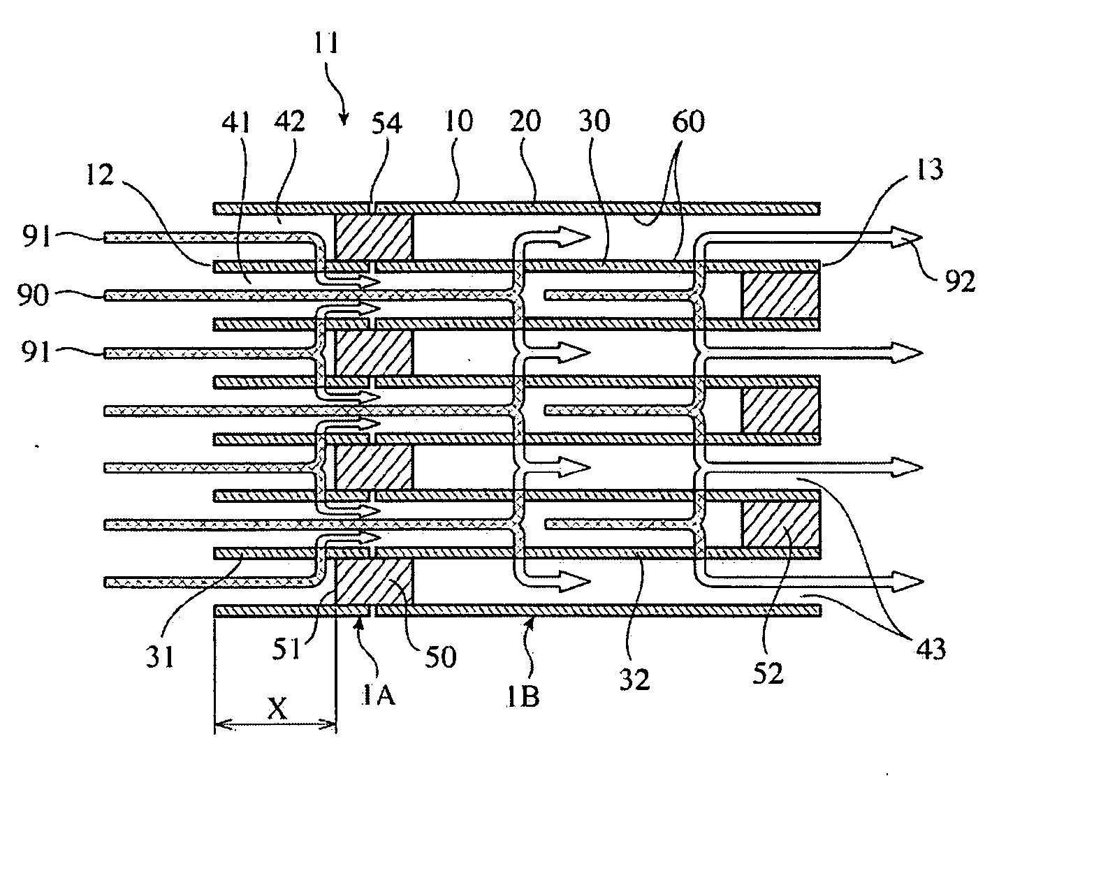
[0076] The powder composition of kaolin, talc, silica, aluminum hydroxide, alumina, etc. was prepared to obtain a cordierite-forming powder comprising, on a mass basis, 47-53% of SiO2, 32-38% of Al2O3, 12-16% of MgO, and 2.5% or less in total of inevitable components (CaO, Na2O, K2O, TiO2, Fe2O3, PbO, P2O5, etc.), and fully mixed with a molding aid, a pore-forming agent, and a predetermined amount of water to prepare a material extrusion-moldable to a honeycomb structure. It was then extrusion-molded by a known extrusion die to produce a honeycomb structure molding comprising a peripheral wall 20, and cell walls 30 inside this peripheral wall 20 for defining flow paths each having a square cross section, which was then dried and sintered to obtain a honeycomb structure 1A with exhaust-gas-inlet-side cell walls 31 and a honeycomb structure 1B with exhaust-gas-outlet-side cell walls 32. Each honeycomb structure had a diameter of 267 mm with 0.3-mm-thick cell walls (porosity: 65%, pitc...

example 6

[0087] A honeycomb structure 1A having a diameter of 267 mm and a total length of 96.4 mm, whose cell walls had a pitch of 1.5 mm, a thickness of 0.3 mm and a porosity of 65%, and a honeycomb structure 1B having a diameter of 267 mm and a total length of 208.3 mm, whose cell walls had a pitch of 1.5 mm, a thickness of 0.3 mm and a porosity of 65%, were produced in the same manner as in Example 2. With a slurry containing a plastic plugging material introduced into the end portions of the flow paths of the honeycomb structures 1A and 1B in a checkerboard pattern, the honeycomb structures 1A and 1B were integrally connected such that a 0.1-mm-wide gap 54 was provided between the cell walls of the honeycomb structures 1A and 1B.

[0088] A resin film was attached to the other end 13 of the honeycomb structure 1B, and provided with apertures alternately with the inlet-side plugs 50. A plugging material slurry was introduced into part of the flow paths of the honeycomb structure and solidi...

example 7

[0090] A honeycomb structure 1A having a diameter of 267 mm and a total length of 96.9 mm, whose cell walls had a pitch of 1.5 mm, a thickness of 0.3 mm and a porosity of 65%, and a honeycomb structure 1B having a diameter of 267 mm and a total length of 206.9 mm, whose cell walls had a pitch of 1.5 mm, a thickness of 0.3 mm and a porosity of 65%, were produced in the same manner as in Example 2. These honeycomb structures were integrally connected by plugs 50 with a 1-mm gap 54, and plugs 52 were formed at the other end 13 of the honeycomb structure 1B alternately with the plugs 50.

[0091] Pt, cerium oxide and active alumina (catalyst B) were carried by the honeycomb structure 1A and the plugs 50, such that the amounts of cerium oxide and active alumina carried were the same as in the catalyst A, and that the amount of Pt carried was 4 g / L. Pt, cerium oxide and active alumina (catalyst C) were carried by the honeycomb structure 1B and the plugs 52, such that the amounts of cerium o...


PUM

PropertyMeasurementUnit
Lengthaaaaaaaaaa
Currentaaaaaaaaaa
Digital informationaaaaaaaaaa

Abstract

A ceramic honeycomb filter comprising pluralities of porous ceramic honeycomb structures 1A, 1B each having large numbers of flow paths 41, 42, 43 partitioned by cell walls 30, which are connected to each other in a flow path direction, desired flow paths being sealed such that an exhaust gas passes through pores of the cell walls 30, the cell walls 31 of at least one honeycomb structure 1A being connected by plugs 50 to the cell walls 32 of a honeycomb structure 1B adjacent thereto with a gap 54 in the flow path direction, and a catalyst being carried by at least part of the cell walls 30 and / or the plugs 50, 52, an exhaust gas-cleaning apparatus comprising the ceramic honeycomb filter and a fuel-adding means disposed upstream thereof, and an exhaust gas-cleaning method using the ceramic honeycomb filter.

Description

FIELD OF THE INVENTION [0001] The present invention relates to a ceramic honeycomb filter suitable for an apparatus for removing particulate matter from an exhaust gas discharged from a diesel engine, an exhaust gas-cleaning apparatus having such a ceramic honeycomb filter, and an exhaust gas-cleaning method. BACKGROUND OF THE INVENTION [0002] To remove carbon-based particulate matter from an exhaust gas discharged from diesel engines, ceramic honeycomb filters comprising ceramic honeycomb structures with pluralities of flow paths alternately sealed at both ends (hereinafter referred to simply as “honeycomb filters”) have recently been put into practical use. [0003] The honeycomb filter usually comprises a porous ceramic honeycomb structure comprising a peripheral wall, and cell walls inside this peripheral wall for defining large numbers of flow paths (hereinafter referred to simply as “honeycomb structure”). Large numbers of flow paths are alternately sealed at ends on the exhaust...

Claims


Application Information

Patent Timeline
IPC IPC(8): F01N3/00B01D46/00B01D46/24B01J35/04
CPCB01D46/0063F01N13/0097B01D46/2455B01D46/2459B01D46/2466B01D46/2474B01D2046/2488B01D2046/2492B01D2046/2496B01J35/04F01N3/0222F01N2330/30F01N2510/0682Y02T10/20B01D46/2451Y02T10/12B01D46/2498B01D46/84B01D46/2482B01J35/56F01N3/02B01D39/14F01N3/022
Inventor SUWABE, HIROHISAWATANABE, KAZUTOYOSUGHARA, HIROYUKITAKAKURA, TAKASHINAKAGOME, KEIICHI
Owner HITACHI METALS LTD
Features
  • Generate Ideas
  • Intellectual Property
  • Life Sciences
  • Materials
  • Tech Scout
  • Unparalleled Data Quality
  • Higher Quality Content
  • 60% Fewer Hallucinations
Learn More