Eureka AIR delivers breakthrough ideas for toughest innovation challenges, trusted by R&D personnel around the world.

Cylinder liners and methods for making cylinder liners

a technology of cylinder liners and cylinder blocks, which is applied in the direction of cylinders, machines/engines, pistons, etc., can solve the problems of non-uniform microstructure of the iron from the outside to the inside of the casting, and undesirable microstructures near the surface of the centrifugal casting technique, etc., to achieve easy machining, easy machining of engine components, and removal of undesirabl

Inactive Publication Date: 2007-12-06
SLINGER MFG
View PDF34 Cites 10 Cited by
  • Summary
  • Abstract
  • Description
  • Claims
  • Application Information

AI Technical Summary

Benefits of technology

[0016]Another advantage of the present invention is that the process provides a suitable mechanical bonding surface on a liner with no undesirable microstructural surface effects. In particular, the process permits machining prior to grit blasting, wherein the machining may remove undesirable surface effects and / or surface defects. The substantial absence of deleterious microstructural surface effects permit easy machining of the inner diameter and / or easy machining of engine components, such as cylinder ports.
[0017]Still another advantage of the present invention is that the process provides a mechanical bonding surface clean and substantially void of any refractory or sand residue from the cylinder liner casting process.
[0018]Still another advantage of the present invention is that the process provides a mechanical bonding surface with machined tolerances that are tighter than as-cast tolerances.
[0019]Still another advantage of the present invention is that machining the outer diameter prior to grit blasting allows for the salvaging of cylinder liner castings that may have defects present on the as-cast surface of the liner castings.
[0020]Still another advantage of the present invention is the machining process that may be used on the outer diameter surface may include machining process that do not utilize chemical or lubricant contact, which may provide machined surfaces having little or no contamination.

Problems solved by technology

While conventional sand casting incorporates insulating sand on the inside diameter and the outside diameter of the solidifying casting which helps to slow the solidification rate, the centrifugal casting technique does not have that advantage.
As a result of the limited insulating contribution of this coating, the high solidification rate of the surface of the centrifugal casting results in undesirable microstructures near the surface of the casting.
Because the heat extraction rates are less severe from the inside to the outside of the solidifying casting, there will be a non-uniform microstructure of the iron from the outside to the inside of the casting.
This undesirable microstructure extending in from the surface of the casting can be very difficult to machine and will not exhibit the desired long wearing properties of the cylinder liner's bore surface for the operation of an engine.
In some cases such impurities can become sufficiently imbedded in the surface of the casting to cause the casting to be scrapped out.
Shot blasting, while roughening the surface, does not create cavities that provide casting material back drafts for mechanical locking or bonding.
While both the methods of the '104 Patent and the '673 Patent provide mechanical bonding between the cylinder liner and the aluminum block, they have some drawbacks.
The use of an as-cast surface brings with it the problems associated with cast iron microstructures near the surface of the casting.
The surface of gray iron castings may include undesirable microstructures formed in the iron because of the faster solidification rates close to the surface of the casting.
If a thin wall cylinder liner is desired to be used with an as-cast outside diameter, such undesirable microstructure resulting from the surface effect may actually extend through the liner cross-section to the inside diameter wear surface of the very thin liner.
The extension of the undesirable microstructure through the liner cross-section may result in both manufacturability problems and / or functional problems for the liner.
Another problem with the above-discussed methods includes the removal of the residual material from the outside of the liners.
In addition, the capability of controlling dimensional tolerances on an as-cast surface (centrifugal or static cast liner) is limited due to casting variables.
As-cast tolerances may not be tight enough to allow a minimum distance between multiple cylinder liners in a block and to provide the optimum uniformity of wall thickness.

Method used


Image

  • Cylinder liners and methods for making cylinder liners
  • Cylinder liners and methods for making cylinder liners
  • Cylinder liners and methods for making cylinder liners

Examples


example

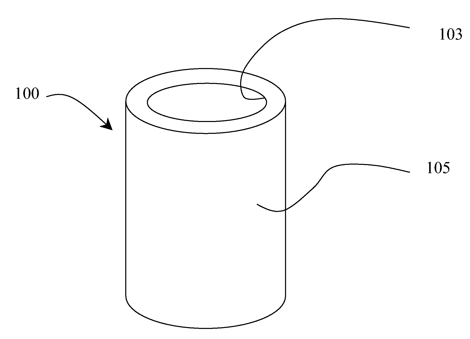
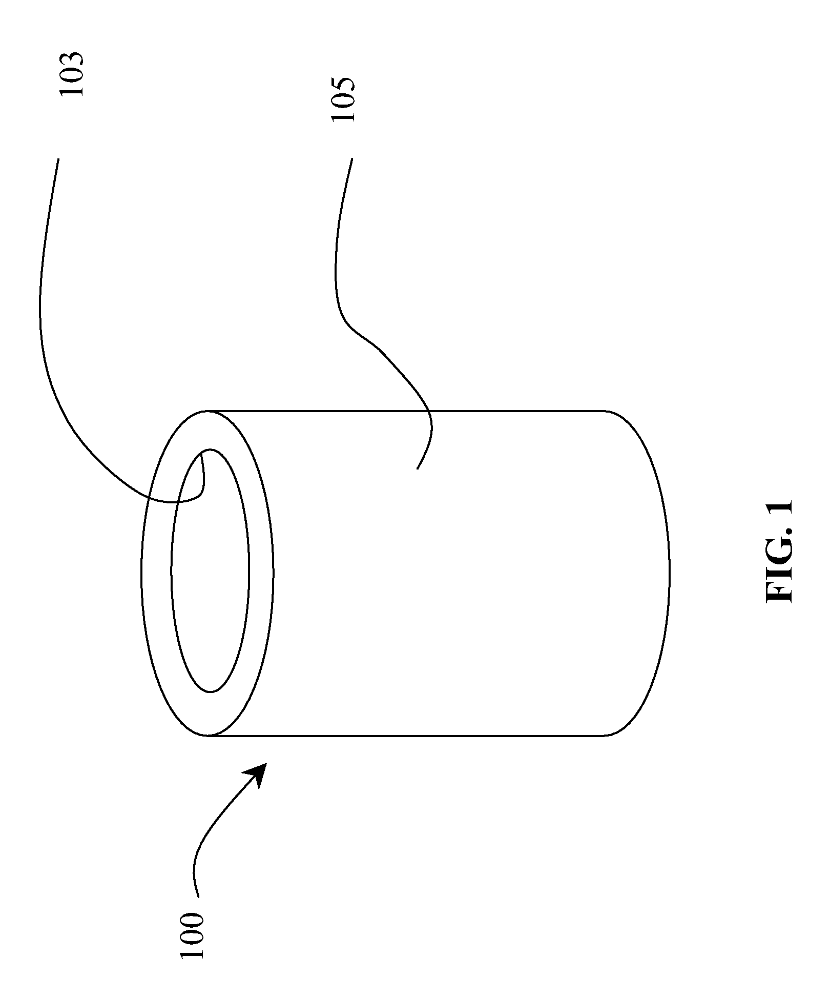
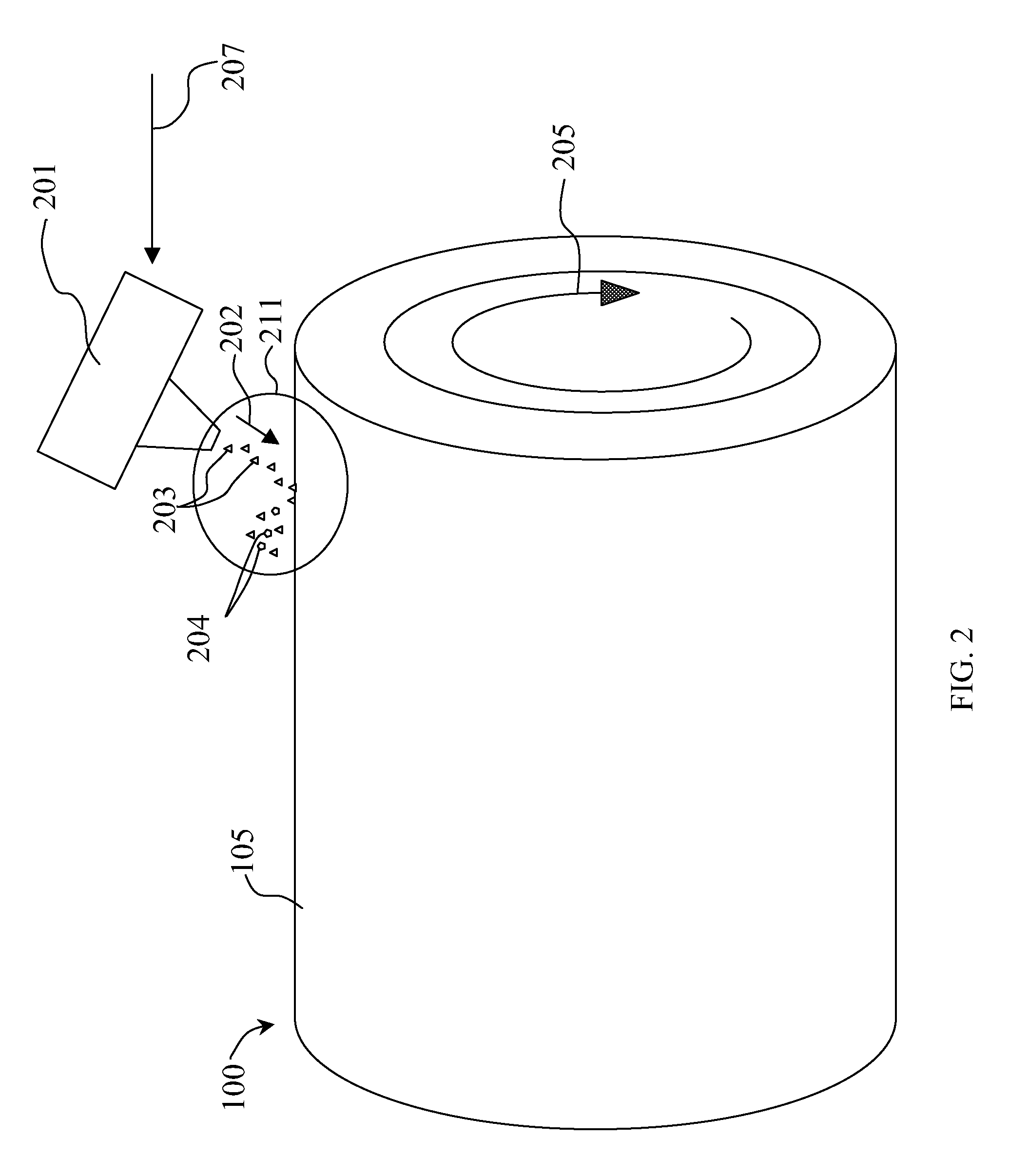
[0049]A cylinder liner according to the present invention was prepared. A cast iron cylinder liner 4.0 inches long and having an outer diameter of 3.5 inches was machined to provide an outer diameter substantially free of surface effects. A grit size G12 was delivered at an angle of 70° with compressed air delivery of 90 psi through a 0.25″ nozzle located 9.0″ away from the surface of the liner. The cylinder liner was rotated at about 60 RPM as the grit was sprayed uniformly along the surface of the liner. The process was continued for about 30 seconds to cover the outer diameter surface of the liner. The cylinder liner 100 produced included cavities peppered along the surface of the outer diameter.

[0050]While the above has been described with respect to cylinder liners 100 and engine blocks 401, the process of the present invention may also find use with cast-in articles requiring strong mechanical bonds and substantially uniform composition and microstructure in the cast-in articl...


PUM

PropertyMeasurementUnit
Thicknessaaaaaaaaaa
Angleaaaaaaaaaa
Microstructureaaaaaaaaaa

Abstract

A method for making cylinder liners and cast engine blocks having cylinder liners having a strong mechanical bond with the engine block. The method includes providing a cast metallic cylinder liner having an outer surface of the cylinder liner. The surface of the cylinder liner is preferably machined to remove surface effects or defects present from the casting process. Grit particles are directed at the outer surface of the cylinder liner with a grit blasting device at a predetermined angle of contact at a sufficient velocity to form cavities on the outer surface. The cavities that are formed have a geometry capable of forming a mechanical bond with the casting material of the engine block.

Description

FIELD OF THE INVENTION[0001]The present invention is directed to cast-in cylinder liners and engine blocks utilizing cast-in cylinder liners.BACKGROUND OF THE INVENTION[0002]Inner walls of the cylinder bores of internal combustion engines are subject to the wearing action of a piston and its seal structure. In engines fabricated from aluminum, aluminum alloys or other lightweight materials, cylinder liners are cast into the bores of the engine block to provide the necessary wear resistance. The casting of cast iron cylinder liners into aluminum blocks allows for excellent iron wearing surfaces in the bores of a lightweight fuel-efficient aluminum block engine.[0003]One known process for inserting the cylinder liners into the engine block includes positioning the cylinder liner in the engine block mold prior to pouring molten metal into the mold cavity to form the engine block. After the casting is complete, these cast-in liners are permanently embedded within the cast metal walls of...

Claims


Application Information

Patent Timeline
IPC IPC(8): F02F1/00
CPCB22D19/0009Y10T29/49272F02F1/004
Inventor HOLTAN, STEVEN T.LIU, SHENGLI
Owner SLINGER MFG
Why Eureka
Eureka Blog
Learn More