Active matrix substrate, reflection type of liquid crystal display and projection type liquid crystal display apparatus

a liquid crystal display and active matrix technology, applied in the direction of instruments, static indicating devices, etc., can solve the problems of consuming a large amount of electric power, large capacitance, and above-described conventional technology, and achieve the effects of reducing the number of necessary terminals, reducing the influence of radiated noise, and high picture quality

Inactive Publication Date: 2007-12-06
CANON KK
View PDF8 Cites 23 Cited by
  • Summary
  • Abstract
  • Description
  • Claims
  • Application Information

AI Technical Summary

Benefits of technology

[0025]A reflection type of liquid crystal display and a projection type liquid crystal display apparatus according to the present invention can provide an output image of high picture quality, by reducing the number of necessar

Problems solved by technology

However, the above described conventional technology had problems described below.
In addition, the liquid crystal display needs wiring for connecting a common signal wire with a pad which connects a common signal wire with an external circuit, and as a result, the common signal wire causes very large capacitance.
As described above, the liquid crystal display needs to drive a la

Method used


Image

  • Active matrix substrate, reflection type of liquid crystal display and projection type liquid crystal display apparatus
  • Active matrix substrate, reflection type of liquid crystal display and projection type liquid crystal display apparatus
  • Active matrix substrate, reflection type of liquid crystal display and projection type liquid crystal display apparatus

Examples


exemplary embodiment 1

[0043]At first, a first exemplary embodiment according to the present invention will be described with reference to FIG. 1 to FIG. 8.

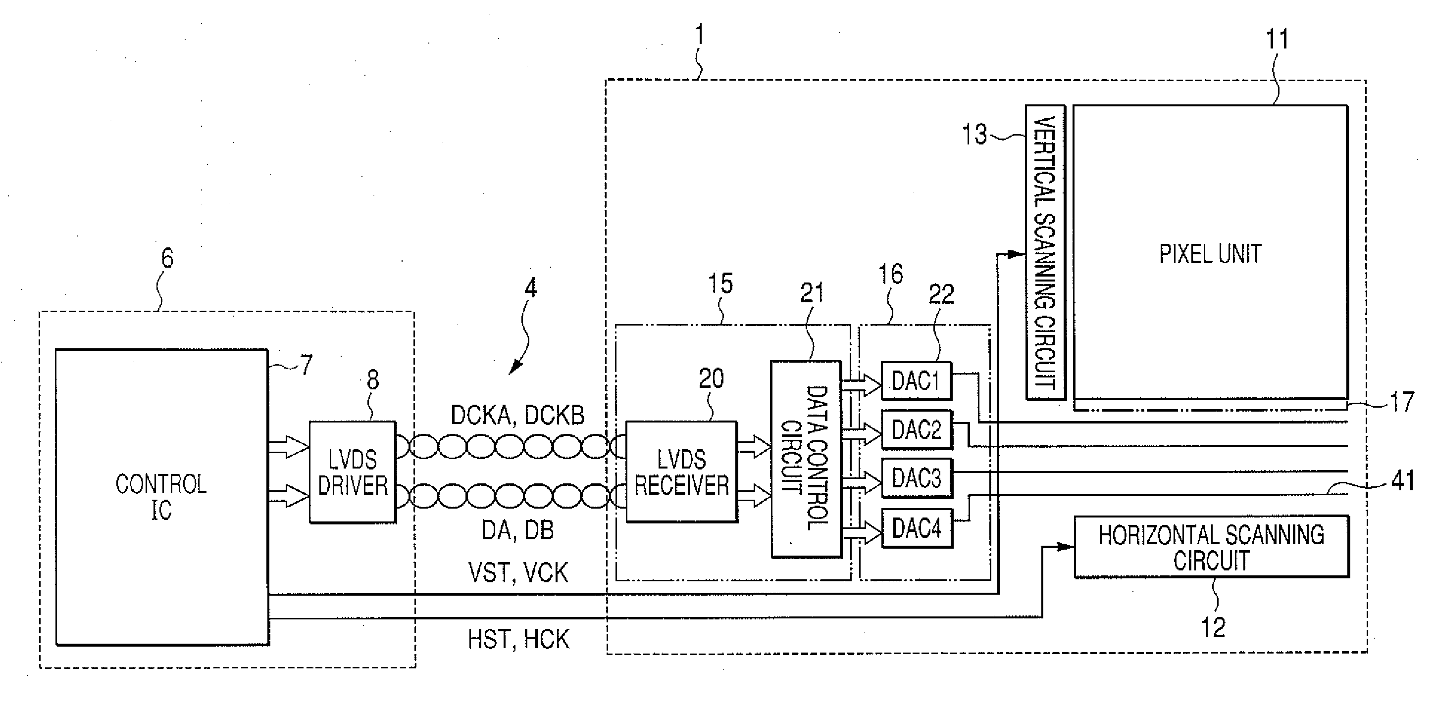
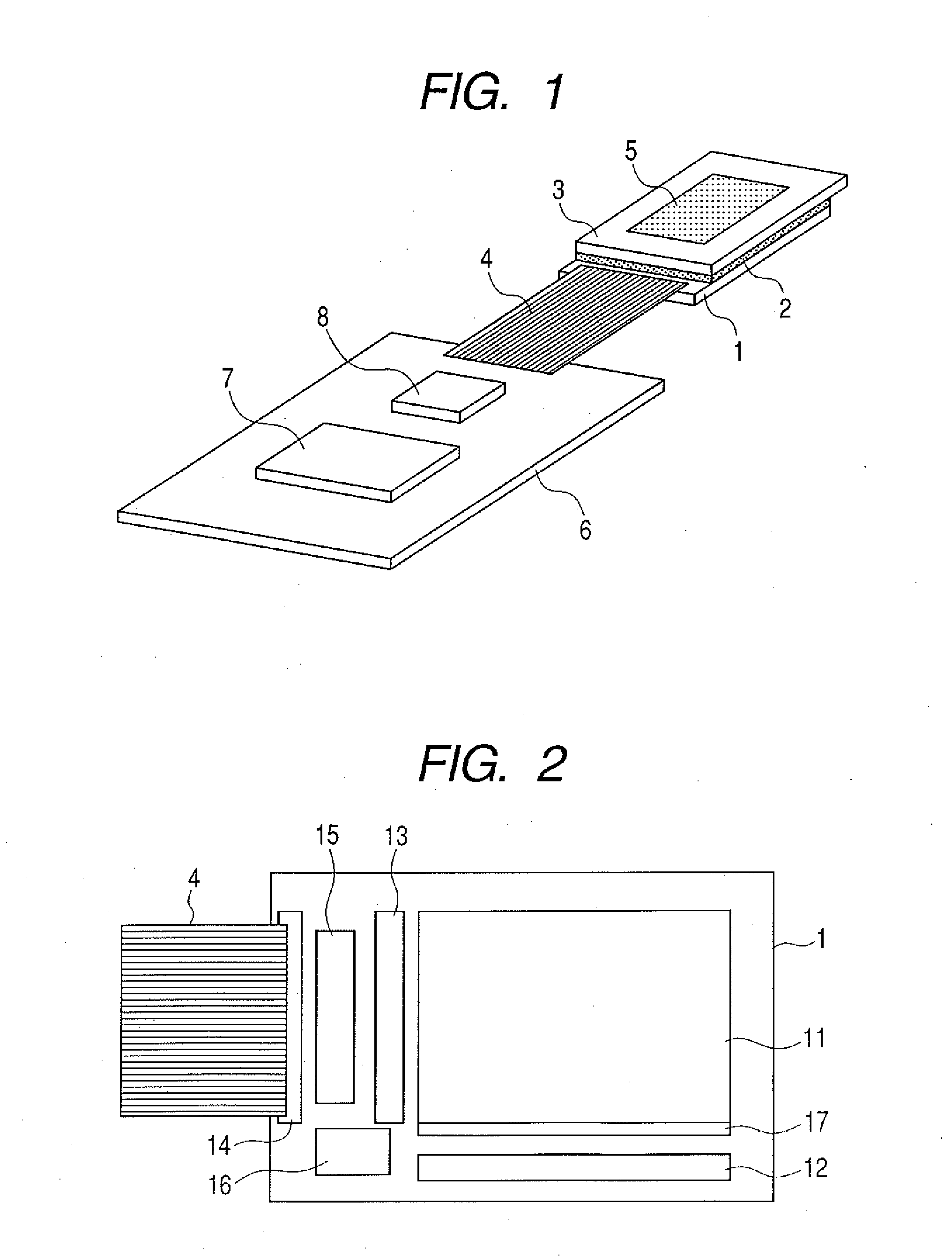
[0044]FIG. 1 diagrammatically illustrates an example of a system of a reflection type of liquid crystal display (display panel) according to the present exemplary embodiment.

[0045]In FIG. 1, reference numeral 1 denotes a silicon substrate (single-crystal semiconductor substrate) which is a substrate for a liquid crystal display (active matrix substrate) integrally formed of a driving circuit and a pixel unit (which will be described later). Reference numeral 3 denotes a transparent electrode (opposite substrate) which works as a common electrode when a liquid crystal inversely driven. Reference numeral 5 denotes a display region. A sealant 2 is arranged in between the silicon substrate 1 and the transparent electrode 3 so as to surround the display region 5. A liquid crystal layer is filled in the space surrounded by the silicon substrate 1, the sealan...

exemplary embodiment 2

[0084]In the next place, a second exemplary embodiment of the present invention will be described with reference to FIG. 9 and FIG. 10.

[0085]In a configuration of the first exemplary embodiment, one LVDS receiver receives DAC data in 4 channels, and accordingly needs to transfer the data at a high rate. For instance, suppose a reflection type of liquid crystal display which has an effective display area of 1,280×800 pixels. Supposing that the display is equipped with a DAC circuit for 8 bits, and reverses signals for 60 frames per second at a double field speed (120 fields per second), the transfer rate exceeds 1 GHz in consideration of horizontal and vertical blanking as well. In order to realize the frequency, the display needs a process for a fine semiconductor with high withstand voltage, which increases a cost.

[0086]The present exemplary embodiment provides a reflection type of liquid crystal display in which the above point is taken into account. In the present exemplary embod...

exemplary embodiment 3

[0093]In the next place, a third exemplary embodiment of the present invention will be described with reference to FIG. 11.

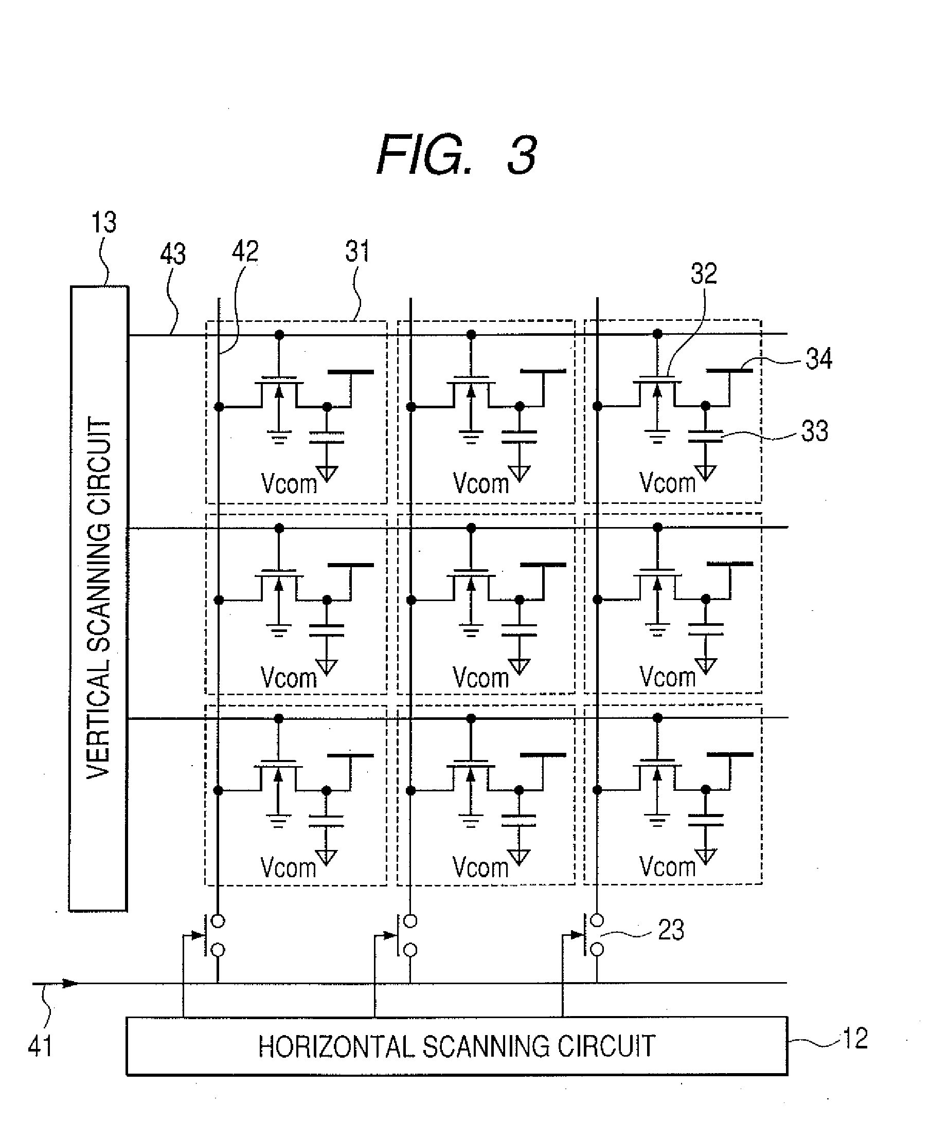
[0094]In a configuration of the second exemplary embodiment, all video wires 41 are arranged in a horizontal direction in an effective pixel region, and accordingly cause large parasitic capacitance which consumes a considerable amount of an electric power. Specifically, an amplitude of voltage necessary for driving a liquid crystal is 10 V or more; the high voltage consumes a considerable amount of an electric power when the parasitic capacitance of the video wire 41 is charged and discharged, and heats a substrate; and the generated heat affects orientation characteristics of the liquid crystal and hinders the display from exhibiting an adequate image.

[0095]The present exemplary embodiment provides a reflection type of liquid crystal display in which the above point is taken into account. In the present exemplary embodiment, a component similar to that in firs...


PUM


Abstract

An object of the present invention is to reduce the number of necessary terminals on a substrate, realize data transmission resistant to disturbance noise even when a source voltage of a logic system for processing a digital video signal is lowered, reduce an influence of a radiated noise, and provide an output image of high picture quality. For that purpose, a reflection type of liquid crystal display has a silicon substrate 1 as an active matrix substrate, uses the digital video signal for a video signal to be input, and converts the digital video signal into an analog video signal in the silicon substrate 1 to provide the output image. The reflection type of liquid crystal display having the above configuration has a DAC circuit 22 for converting the input digital video signal into the analog video signal; and an LVDS receiver 20 which receives each digital video signal that is to be input into the DAC circuit 22, through a LVDS transmission. The LVDS receiver 20 is mounted on the same silicon substrate 1 as the DAC circuit 22 is mounted.

Description

BACKGROUND OF THE INVENTION[0001]1. Field of the Invention[0002]The present invention relates to an active matrix substrate, a reflection type of liquid crystal display and a projection type liquid crystal display apparatus, and particularly relates to the reflection type of liquid crystal display having the active matrix substrate formed with the use of a single-crystal semiconductor substrate.[0003]2. Description of the Related Art[0004]In recent years, a liquid crystal display has been widely used for a small display device and a terminal of so-called office automation equipment, and particularly a projection type liquid crystal display apparatus for projecting an image on a large screen has been popularly used in the field of the office automation equipment.[0005]This type of projection type liquid crystal display apparatus is generally classified into a light transmitting type of a liquid crystal and a reflection type of liquid crystal display. The light transmitting type of th...

Claims


Application Information

Patent Timeline
IPC IPC(8): G09G3/36
CPCG09G3/2096
Inventor OOMURA, MASANOBU
Owner CANON KK
Why Eureka
Try Eureka