Fuel Cell System

a fuel cell and system technology, applied in the direction of fuel cells, solid electrolyte fuel cells, electrical equipment, etc., can solve the problems of water vapor in the anode and cathode, the need to remove hydrogen gas from the fuel cell during shut-down, and the need to reduce the catalytic ability of the electrode, so as to achieve high reliability and suppress the degradation of the strength of the solid polymer membrane

Active Publication Date: 2007-12-20
PANASONIC CORP
View PDF8 Cites 6 Cited by
  • Summary
  • Abstract
  • Description
  • Claims
  • Application Information

AI Technical Summary

Benefits of technology

[0026] According to the present invention, during operation and during purging, the pressure on one of the anode-side and the cathode-side of the electrolyte membrane is controlled such that it is constantly larger than the pressure on the other side. It is therefore possible to suppress degradation of the strength of the solid polymer membrane caused by the vibration thereof which occurs during start-up or shut-down purging. Accordingly, it is possible to provide a fuel cell system having a high reliability in a long-term operation that is subject to start-ups and shut-downs.

Problems solved by technology

Thus, in order to maintain the high power generation performance, the water produced by the reaction of formula (2) alone is insufficient, and it is thus necessary to supply water from outside.
Also, the operation temperature of this fuel cell is usually 90° C. or lower, because there are limitations resulting from the heat-resisting performance of the solid polymer membrane serving as the electrolyte.
However, in starting up and shutting down the fuel cell which is a power generation source, the following problems arise, so the gas supplied to one or both of the anode and the cathode needs to be replaced, i.e., purged, with an inert gas.
First, in terms of safety, a problem associated with the start-up and shut-down is that hydrogen gas needs to be removed from the fuel cell during shut-down.
This potential causes oxidation reaction or dissolution reaction of platinum serving as the electrode catalyst, thereby lowering the catalyzing ability of the electrode.
Third, in terms of start-up stability, water vapor in the anode and cathode needs to be removed.
The condensed water covers the platinum surface, clogs the pores of the porous gas diffusion layer, and closes the gas flow channel of the separator, so that the gas diffusion is hampered, thereby resulting in unstable power generation upon start-up.

Method used


Image

  • Fuel Cell System
  • Fuel Cell System
  • Fuel Cell System

Examples


embodiment 1

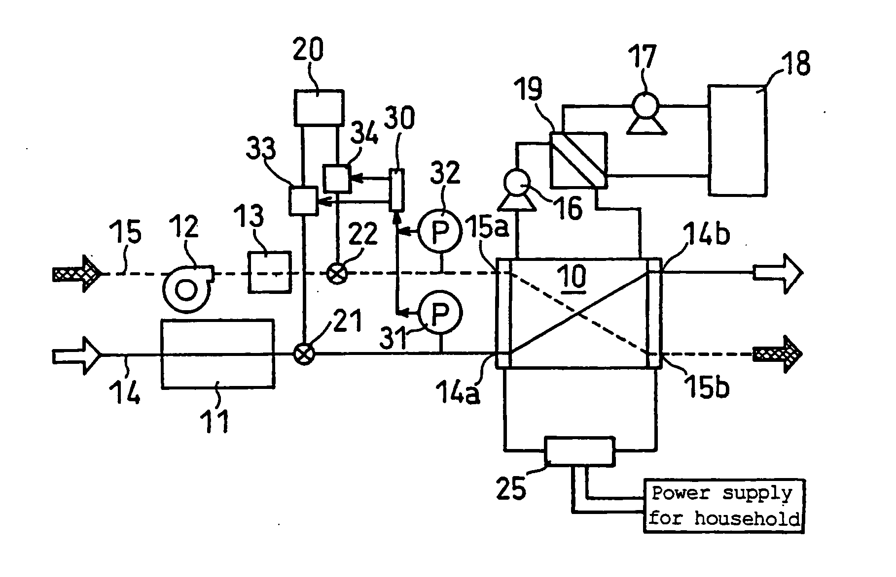
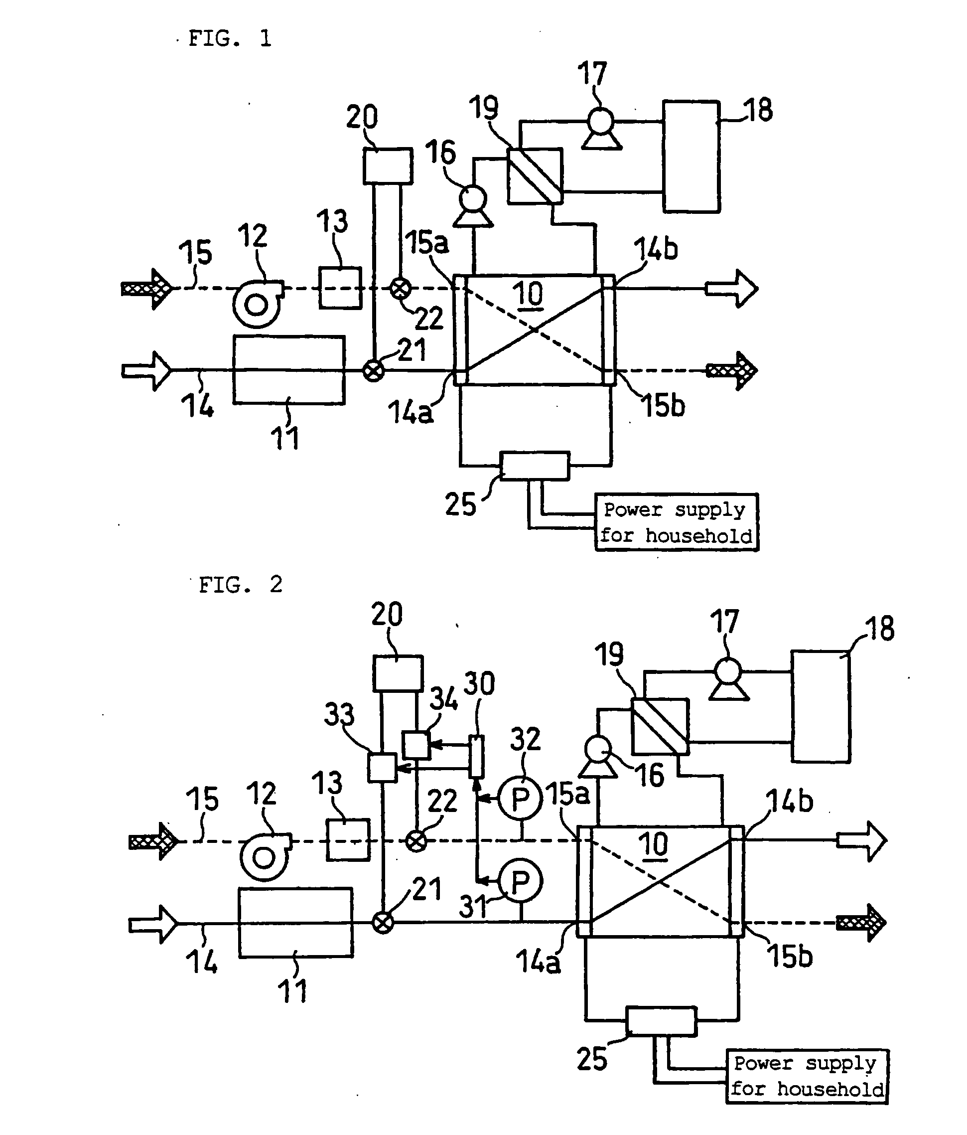
[0036]FIG. 2 is a diagram showing the structure of a fuel cell system according to Embodiment 1 of the present invention.

[0037] The fuel cell system of Embodiment 1 includes a solid polymer type fuel cell 10 that generates electric power using a fuel gas and an oxidant gas, hydrogen supply means 11 for producing a hydrogen-rich gas by steam-reforming of a raw material such as natural gas and supplying it to the fuel cell 10, air supply means 12 for taking in outside air as an oxidant gas, and a humidifier 13 for humidifying the air as appropriate. It also includes a pump 16 for circulating cooling water to collect the heat generated during the power generation of the fuel cell 10, a heat exchanger 19 for collecting / storing the thermal energy collected from the cooling water, a hot water reservoir 18, a circulation pump 17 for circulating the water in the hot water reservoir 18 through the heat exchanger 19, and an inverter 25 for converting the direct current generated by the fuel ...

embodiment 2

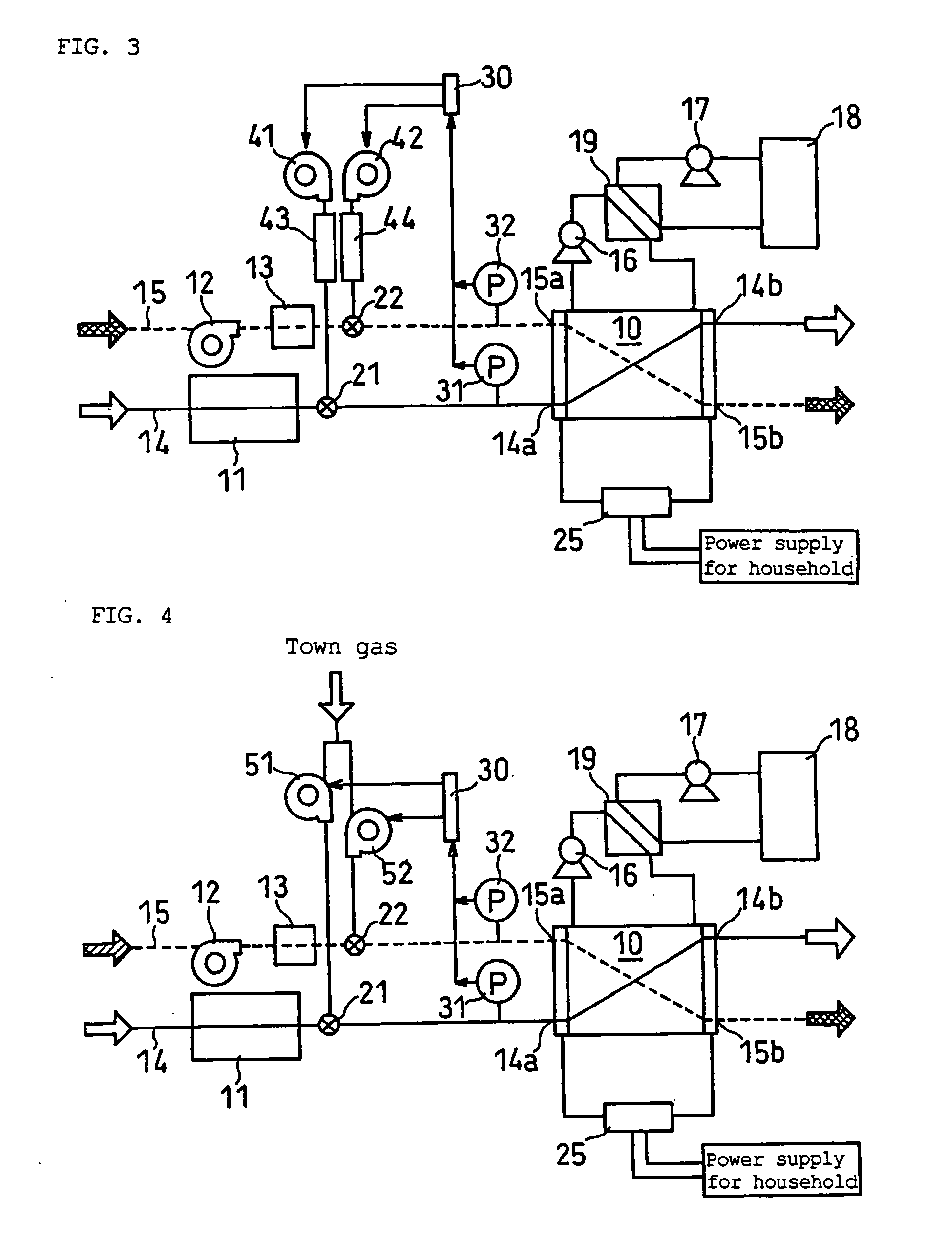
[0052]FIG. 3 is a diagram showing the structure of a fuel cell system according to Embodiment 2 of the present invention.

[0053] The fuel cell system of Embodiment 2 has blowers 41 and 42, instead of the inert gas cylinder 20, in the conventional system as described in Embodiment 1. The air introduced into the system by the blowers 41 and 42 from the outside is passed through combustors 43 and 44, so that oxygen in the air is consumed and nitrogen gas serving as the inert gas is produced. This gas is supplied to the fuel cell as the purge gas. Further, the system is equipped with the manometers 31 and 32 for measuring the pressure in the fuel gas flow path 14 on the inlet 14a side and the pressure in the air flow path 15 on the inlet 15a side, and the controller 30 for storing the pressures measured by the manometers 31 and 32 and controlling the outputs of the blowers 41 and 42 based on the measured values.

[0054] The purge sequence of Embodiment 2 for shut-down is described below....

embodiment 3

[0066]FIG. 4 is a diagram showing the structure of a fuel cell system according to Embodiment 3 of the present invention.

[0067] The fuel cell system of Embodiment 3 has booster pumps 51 and 52, instead of the inert gas cylinder 20, in the conventional system as described in Embodiment 1. The town gas introduced into the system by the booster pumps 51 and 52 from the outside is supplied to the fuel cell as the inert gas. Further, the system is equipped with the manometers 31 and 32 for measuring the pressure in the fuel gas flow path 14 on the inlet 14a side and the pressure in the air flow path 15 on the inlet 15a side, and the controller 30 for storing the pressures measured by the manometers 31 and 32 and controlling the outputs of the booster pumps 51 and 52 based on the measured values.

[0068] The purge sequence of Embodiment 3 for shut-down is described below.

[0069] When the demand for power from the external circuit disappears and a stop signal is sent to the fuel cell syste...


PUM

PropertyMeasurementUnit
temperatureaaaaaaaaaa
current densityaaaaaaaaaa
shut-down timeaaaaaaaaaa

Abstract

A fuel cell system includes a fuel cell that is subjected to a purge operation of supplying an inert gas to an anode and/or cathode upon shut-down of the fuel cell. The differential pressure ΔP is defined as ΔP=Pa−Pc where Pa is the pressure in an inlet-side flow path leading to the anode and Pc is the pressure in an inlet-side flow path leading to the cathode. The differential pressure during the purge operation is controlled such that the differential pressure during operation ΔPo and the differential pressure during the purge operation ΔPp satisfy the relation: 0<ΔPo×ΔPp. This makes it possible to reduce the stress exerted on a solid electrolyte membrane and improve the long-term reliability of the fuel cell.

Description

TECHNICAL FIELD [0001] The present invention relates to a fuel cell system that generates electric power using a solid polymer fuel cell. BACKGROUND ART [0002] Fuel cells are basically composed of a pair of electrodes, i.e., anode and cathode, sandwiching an ion-conductive electrolyte, and an anode-side separator and a cathode-side separator sandwiching the electrodes. The anode-side separator has a flow channel for supplying a fuel to the anode, while the cathode-side separator has a flow channel for supplying an oxidant to the cathode. By supplying the anode with a fuel, such as hydrogen gas or ethanol, and supplying the cathode with an oxidant such as oxygen or air, the chemical energy of these reactive substances is converted to electrical energy through oxidation or reduction reaction on the electrodes, to produce current. [0003] A type of fuel cell uses a hydrogen-ion conductive polymer membrane as the electrolyte, uses hydrogen or a mixed gas composed mainly of hydrogen as th...

Claims


Application Information

Patent Timeline
Patent Type & Authority Applications(United States)
IPC IPC(8): H01M8/04H01M8/10
CPCH01M8/04104Y02E60/50H01M8/04231H01M8/04
Inventor SHIBATA, SOICHIURATA, TAKAYUKISUGAWARA, YASUSHIUMEDA, TAKAHIROMORITA, JUNJIHATOH, KAZUHITOKITANO, YUKINOBU
Owner PANASONIC CORP
Why Eureka
Try Eureka