Pellicle

a lithography and pellicle technology, applied in the field of lithography, can solve the problems of difficult to always keep the exposure master plate clean, affect the yield of semiconductors, and affect the quality of the exposure, so as to reduce the amount of water-soluble ions and reduce the amount of outgassing

Inactive Publication Date: 2007-12-20
SHIN ETSU CHEM IND CO LTD
View PDF7 Cites 39 Cited by
  • Summary
  • Abstract
  • Description
  • Claims
  • Application Information

AI Technical Summary

Benefits of technology

[0009]It is an object of the present invention to provide a pellicle for which the formation of haze due to ammonium sulfate, etc. is suppressed by reducing the amount of water-soluble ion and reducing the amount of outgassing.
[0011]The present inventors have further found that forming a polymer coating on the surface of an aluminum alloy frame is effective; furthermore, it is preferable to employ electrodeposition coating for forming the polymer coating, and it is more preferable to employ anionic electrodeposition coating using a thermosetting resin. In accordance with these means, a pellicle that reduces the release of an acid such as sulfuric acid, nitric acid, or an organic acid contained in a conventional anodized coating can be prepared, and a pellicle having a low incidence of haze even under an exposure environment of short UV rays has thus been accomplished.
[0023]Providing a polymer coating on a pellicle frame made of an aluminum alloy enables a pellicle having a reduced content of sulfate ion, nitrate ion, organic acid, etc. to be provided. This has the effect of making it possible to cope with lithography employing a shorter wavelength by suppressing the occurrence of haze by reducing the content of sulfate ion, nitrate ion, organic acid, etc. contained in an anodized coating, which is a problem of the conventionally used pellicle frame with an anodized aluminum alloy surface, and by suppressing the amount of gas containing the acids that is generated from the pellicle frame.
[0024]The merit over cationic electrodeposition coating using a thermosetting resin is that the amount of gas generated from the frame surface during electrodeposition coating is smaller for the anionic type, and it is therefore possible to decrease the frequency of pin holes, etc. occurring on the surface.
[0025]It is also easy to remove attached foreign particles from the pellicle of the present invention.

Problems solved by technology

In the production of a semiconductor such as an LSI or a ULSI or the production of a liquid crystal display panel, patterning is formed by irradiating a semiconductor wafer or a liquid crystal master plate with light; if debris is attached to an exposure master plate (lithography mask) used here, since the debris absorbs the light or bends the light, there are the problems that the replicated pattern is deformed, the edge becomes rough, or the background is stained black, thus impairing the dimensions, quality, appearance, etc.
Because of this, these operations are normally carried out in a clean room, but even within a clean room it is difficult to always keep the exposure master plate clean, and a method is therefore employed in which a pellicle that allows exposure light to easily pass through is adhered to the surface of the exposure master plate to act as a debris shield.
However, cloudy foreign matter, called haze, formed on the mask substrate cannot completely be prevented from occurring even by washing the reticle or reducing the amount of gas generated from the materials forming the pellicle, and this causes a decrease in the yield in semiconductor production.

Method used


Image

  • Pellicle
  • Pellicle

Examples


example 1

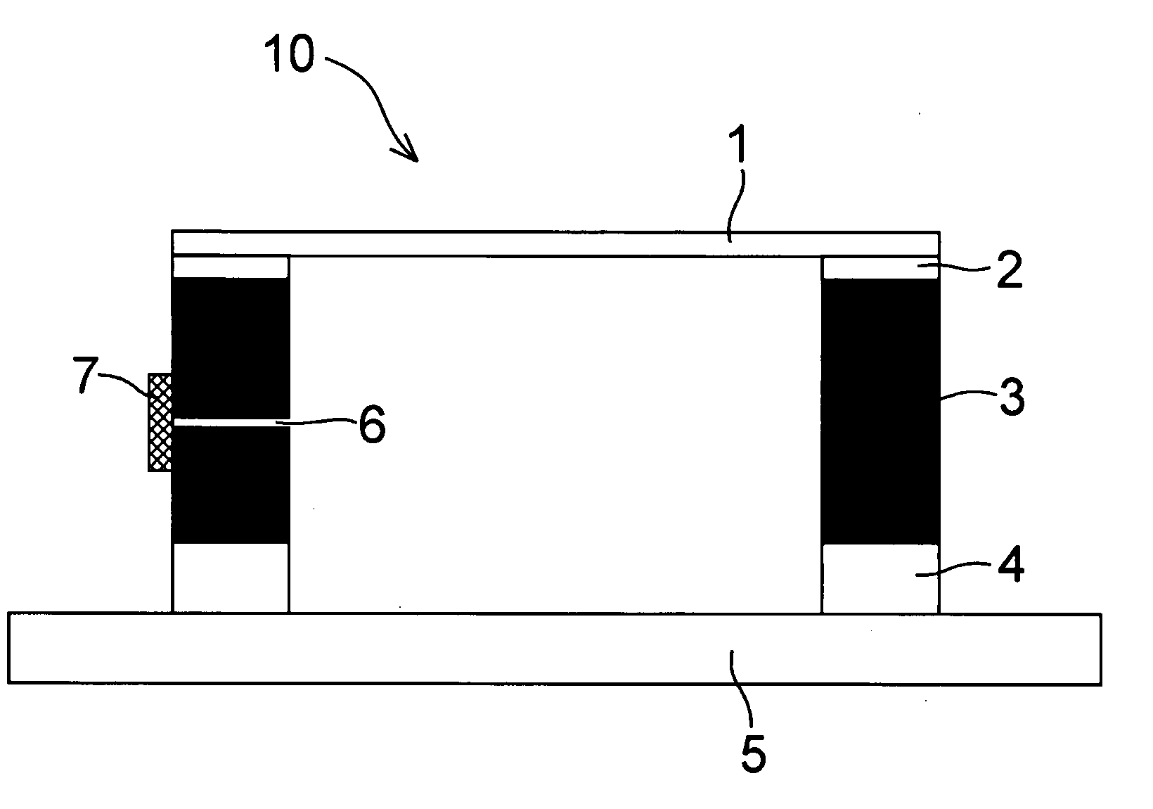
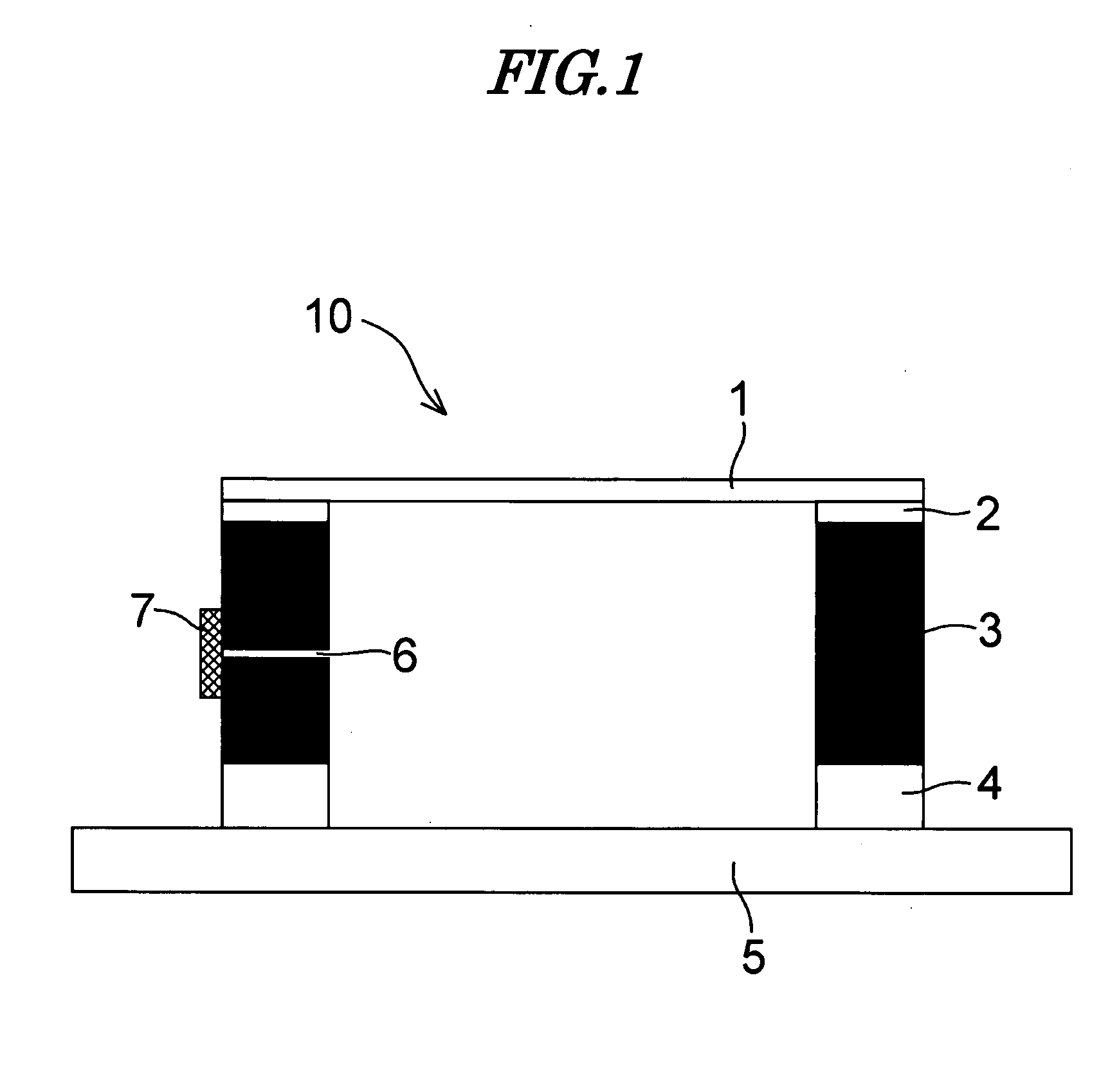
[0057]First, as a pellicle frame, a frame was prepared using an A7075-T651 aluminum alloy so that the frame outer dimensions were 149 mm×122 mm×5.8 mm and the frame thickness was 2 mm. A vent having a diameter of 0.5 mm was provided in the middle on one side face of the frame.

[0058]After the surface of the frame was washed, the surface was roughened by subjecting it to a surface treatment for 1 minute employing a sandblasting machine using glass beads with a discharge pressure of 1.5 kg / cm2. Subsequently, the surface was etched by immersing it in an alkaline solution and then washed with water. After rinsing with pure water, it was subjected to electrodeposition coating with an Elecoat Frosty W-2 solution adjusted to 25° C. (Shimizu Co., Ltd; thermosetting anionic type, matte type; black paint) so that the coating thickness would be 5 μm (since the coating thickness depended on the condition of the solution, a dummy frame was fed in advance, and the voltage and time for the electrod...

example 2

[0068]In the same manner as in Example 1, as a pellicle frame, a frame was prepared using an A7075-T651 aluminum alloy so that the frame outer dimensions were 149 mm×122 mm×5.8 mm and the frame thickness was 2 mm. A vent having a diameter of 0.5 mm was provided in the middle on one side face of the frame.

[0069]After the surface of the pellicle frame was washed, the surface was roughened by subjecting it to a surface treatment for 1 minute employing a sandblasting machine using glass beads with a discharge pressure of 1.5 kg / cm2. Subsequently, the surface was etched by immersing it in an alkaline solution and then washed with water. After rinsing with pure water, it was subjected to electrodeposition coating with an Elecoat Frosty W-2 solution adjusted to. 25° C. (Shimizu Co., Ltd) so that the coating thickness would be 18 μm (since the coating depended on the condition of the solution, a dummy frame was fed in advance, and the voltage and time for the electrodeposition step were det...

example 3

[0078]In the same manner as in Example 1, as a pellicle frame, a frame was prepared using an A7075-T651 aluminum alloy so that the frame outer dimensions were 149 mm×122 mm×5.8 mm and the frame thickness was 2 mm. A vent having a diameter of 0.5 mm was provided in the middle on one side face of the frame.

[0079]After the surface of the frame was washed, the surface was roughened by subjecting it to a surface treatment for 1 minute employing a sandblasting machine using glass beads with a discharge pressure of 1.5 kg / cm2. Subsequently, the surface was etched by immersing it in an alkaline solution and then washed with water. After rinsing with pure water, it was subjected to electrodeposition coating with an Elecoat Frosty W-2 solution adjusted to 25° C. (Shimizu Co., Ltd) so that the coating thickness would be 3 μm. After shower-rinsing with pure water, a heat treatment was carried out in an oven at 200° C. for 30 minutes.

[0080]When analysis was carried out in the same manner as in E...


PUM

PropertyMeasurementUnit
emissivityaaaaaaaaaa
thicknessaaaaaaaaaa
thicknessaaaaaaaaaa

Abstract

A pellicle is provided that includes an aluminum alloy pellicle frame having a polymer coating on the surface and a pellicle film stretched over the pellicle frame. There is also provided a process for producing the pellicle in which the polymer coating is an electrodeposition-coated film, the process including a step of roughening the surface of the aluminum alloy pellicle frame by sandblasting, a step of etching the surface of the pellicle frame with an alkali solution, a step of electrodeposition coating the pellicle frame, and a step of stretching the pellicle film over the pellicle frame.

Description

BACKGROUND OF THE INVENTION[0001]1. Field of the Invention[0002]The present invention relates to a pellicle for lithography that is used as a debris shield for a lithography mask when producing a liquid crystal display panel or a semiconductor device such as an LSI or a ULSI.[0003]2. Description of the Related Art[0004]In the production of a semiconductor such as an LSI or a ULSI or the production of a liquid crystal display panel, patterning is formed by irradiating a semiconductor wafer or a liquid crystal master plate with light; if debris is attached to an exposure master plate (lithography mask) used here, since the debris absorbs the light or bends the light, there are the problems that the replicated pattern is deformed, the edge becomes rough, or the background is stained black, thus impairing the dimensions, quality, appearance, etc.[0005]Because of this, these operations are normally carried out in a clean room, but even within a clean room it is difficult to always keep t...

Claims


Application Information

Patent Timeline
Patent Type & Authority Applications(United States)
IPC IPC(8): G03F1/00G03F1/62G03F1/64
CPCG03F1/64B29C37/0075G03F7/70983
Inventor HAMADA, YUICHI
Owner SHIN ETSU CHEM IND CO LTD
Why Eureka
Try Eureka