
Infrared Absorption Filter

Active Publication Date: 2007-12-20
OSAKA GAS CO LTD
View PDF6 Cites 11 Cited by
  • Summary
  • Abstract
  • Description
  • Claims
  • Application Information

AI Technical Summary

Benefits of technology

[0008] It is therefore an object of the present invention to provide an infrared absorption filter which enables a coloring matter having infrared absorptivity (may be referred to as “IRCM” hereinafter) to be contained or dispersed uniformly in a high concentration and has high durability as well as an infrared absorption panel comprising this infrared absorption filter.
[0013] The present invention is a method of improving the environmental resistance of an infrared absorption filter containing a resin having a fluorene skeleton and a coloring matter having infrared absorptivity, wherein a polycarbonate resin containing 20 to 100 mol % of a recurring unit represented by the above formula (1) and 0 to 80 mol % of a recurring unit represented by the above formula (2) is used as the resin having a fluorene skeleton.
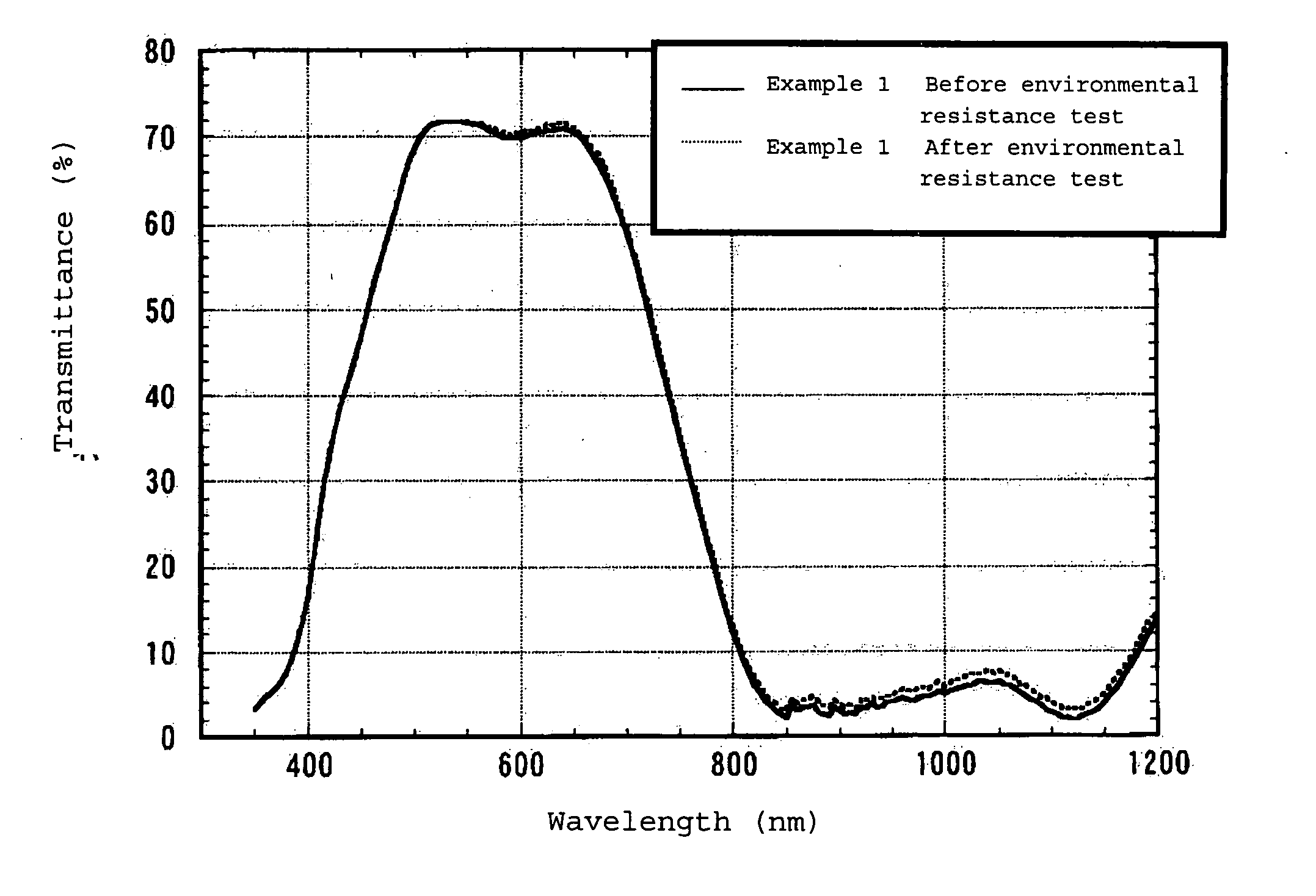
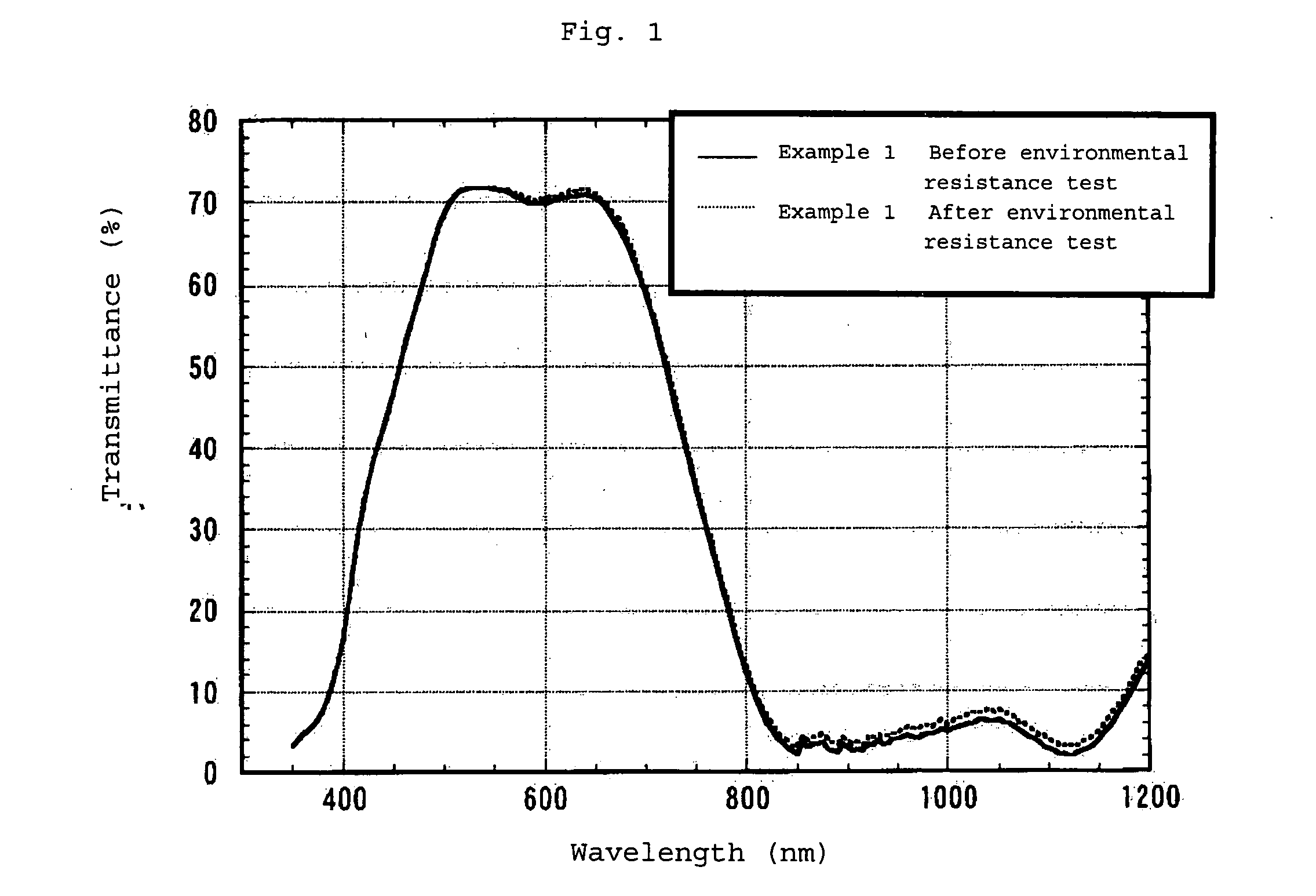
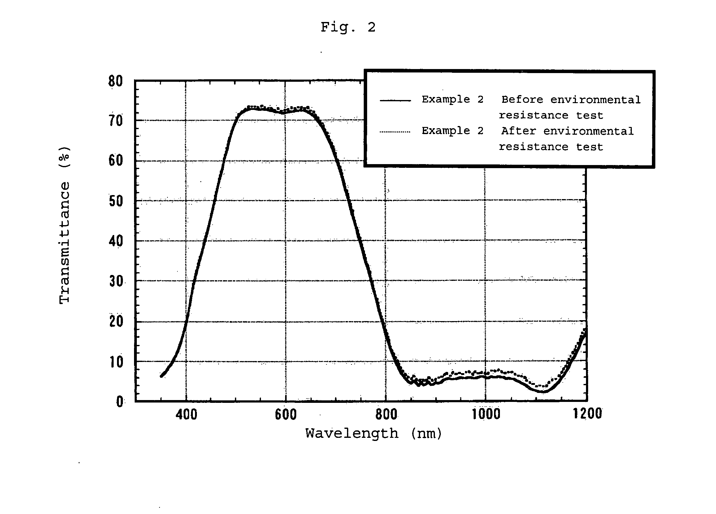
[0015] The infrared absorption filter of the present invention enables IRCM to be dispersed in FLPC uniformly in a high concentration and the agglomeration of the coloring matter and a reaction between the coloring matters to be suppressed when FLPC is used. Therefore, a film as thin as about several tens of μm can intercept infrared radiation and transmit visible radiation. Since IRCM is stabilized in FLPC, its deterioration by heat, light and water can be markedly suppressed and the infrared absorption filter of the present invention can keep stable performance for a long time. According to the present invention, there is provided an infrared absorption panel comprising this infrared absorption filter. Further, according to the present invention, the environmental resistance of the infrared absorption filter comprising a resin having a fluorene skeleton and a coloring matter having infrared absorptivity can be significantly improved.

Problems solved by technology

However, these glass infrared absorption filters are heavy, easily broken and hard to be processed, for example, bent.
However, the above transparent resins which are well known as the binder resin are not satisfactory in terms of the above function, and various resins are proposed instead.
Also, there remains a problem with the durability of the obtained infrared absorption filter.

Method used


Image

  • Infrared Absorption Filter
  • Infrared Absorption Filter
  • Infrared Absorption Filter

Examples


synthesis example 1

[0130] 9,810 parts of ion exchange water and 1,930 parts of a 48% aqueous solution of sodium hydroxide were added to a reactor equipped with a thermometer, stirrer and reflux condenser, 1,065 parts of 2,2-bis(4-hydroxyphenyl)propane, 1,177 parts of 9,9-bis(4-hydroxy-3-methylphenyl)fluorene and 4.5 parts of sodium hydrosulfite were dissolved in the resulting solution, 6,610 parts of methylene chloride was added, and 1,000 parts of phosgene was blown into the reactor for 60 minutes under agitation at 16 to 20° C. After phosgene was blown, 50.2 part of p-tert-butylphenol and 317 parts of a 48% aqueous solution of sodium hydroxide were added, and 0.94 part of triethylamine was further added and stirred at 20 to 27° C. for 40 minutes to terminate a reaction. A methylene chloride layer containing the reaction product was washed with diluted hydrochloric acid and pure water, and methylene chloride was evaporated to obtain FLPC. The obtained FLPC contained 40 mol % of a recurring unit havin...

synthesis example 2

[0131] 10,120 parts of ion exchange water and 1,857 parts of a 48% aqueous solution of sodium hydroxide were added to a reactor equipped with a thermometer, stirrer and reflux condenser, 512.8 parts of 2,2-bis(4-hydroxyphenyl)propane, 1,984 parts of 9,9-bis(4-hydroxy-3-methylphenyl)fluorene and 4.3 parts of sodium hydrosulfite were dissolved in the resulting solution, 7,632 parts of methylene chloride was added, and 1,000 parts of phosgene was blown into the reactor for 60 minutes under agitation at 16 to 20° C. After phosgene was blown, 33.7 parts of p-tert-butylphenol and 353 parts of a 48% aqueous solution of sodium hydroxide were added, and 0.95 part of triethylamine was further added and stirred at 20 to 27° C. for 40 minutes to terminate a reaction. A methylene chloride layer containing the reaction product was washed with diluted hydrochloric acid and pure water, and methylene chloride was evaporated to obtain FLPC. The obtained FLPC contained 70 mol % of a recurring unit hav...

synthesis example 3

[0132] 1,000 parts of 9,9-bis[4-(2-hydroxyethoxy)phenyl]fluorene, 503 parts of diphenyl carbonate, 0.10 part of tetramethylammonium hydroxide and 0.0018 part of sodium hydroxide were fed to a reactor equipped with a stirrer, distiller and decompressor, the inside of the reactor was substituted by nitrogen, and these substances were dissolved at 140° C. After 30 minutes of agitation, a reaction was carried out for 30 minutes by gradually increasing the inside temperature to 180° C. and reducing the pressure to 1.33×10⁴ Pa, and the formed phenol was distilled off. The temperature was kept increased by maintaining the same pressure to distill off phenol at 200° C. for 30 minutes, at 220° C. for 30 minutes, at 240° C. for 30 minutes and further at 260° C. for 20 minutes. Subsequently, the pressure was gradually reduced, stirring was carried out at 260° C. and 133 Pa or less for 4 hours, and the product was taken out from the reactor to obtain FLPC. The obtained FLPC was composed of a fl...


PUM

PropertyMeasurementUnit
Percent by massaaaaaaaaaa
Massaaaaaaaaaa

Abstract

It is an object of the present invention to provide an infrared absorption filter which enables a coloring matter having infrared absorptivity to be contained or dispersed uniformly in a high concentration and has excellent durability and an infrared absorption panel comprising this infrared absorption filter. The infrared absorption filter is composed of a polycarbonate resin which contains 20 to 100 mol % of a recurring unit having a fluorene skeleton represented by the formula (1) and 0 to 80 mol % of a recurring unit represented by the formula (2) and a coloring matter having infrared absorptivity.

Description

TECHNICAL FIELD [0001] The present invention relates to an infrared absorption filter containing a coloring matter having infrared absorptivity and to an infrared absorption panel comprising this infrared absorption filter. BACKGROUND ART [0002] A filter composed of glass having a deposited film thereon and a filter composed of phosphate glass containing metal ions are known as infrared absorption filters. However, these glass infrared absorption filters are heavy, easily broken and hard to be processed, for example, bent. [0003] To overcome these defects, a plastic infrared absorption filter is now under study and many materials are proposed. For example, JP-A 2000-227515 (patent document 1) discloses an infrared absorption filter prepared by forming a coating layer made of a composition containing an infrared absorbing coloring matter dispersed in a binder resin on a base material, wherein the amount of the residual solvent in the laminate is 5.0 wt % or less. In this document, po...

Claims


Application Information

Patent Timeline
IPC IPC(8): G02B5/22C08G64/06C09B47/08C09B47/30C09B53/00C09B57/10C09K3/00
CPCC08G64/0208C08G64/04C08G64/1608C08J5/18C08J2369/00C08K5/0041G02B5/208C09B47/08C09B47/30C09B53/02C08L69/00C08G64/06G02B5/22
Inventor YAMADA, MASAHIROFUJIKI, TSUYOSHIKAWASAKI, SHINICHIYAMADA, MITSUAKIYANAGIDA, TAKATSUNEANDO, MASATOSHIIMANAKA, YOSHIHIKO
Owner OSAKA GAS CO LTD
Learn More