Power Transmission Mechanism for Conversion Between Linear Movement and Rotary Motion

Inactive Publication Date: 2007-12-27
XIAMEN TUXIAN ENERGETIC SCI & TECH
View PDF8 Cites 8 Cited by
  • Summary
  • Abstract
  • Description
  • Claims
  • Application Information

AI Technical Summary

Benefits of technology

[0013] The roller shaft of the present invention provides a plurality of segments which extend from the center to the periphery spaced at a equal angle, as shown as the roller shaft in FIGS. 5a to 5d and FIGS. 7a to 7f, said roller shaft having a through hole 55 at the center. The cross section of the segments of the above described roller shaft has rectangular or H shape at positions where the rollers are installed. Said roller shaft may be formed with steel or aluminum-titanium alloy having light weight and high strength, or may include carbon fiber and other nonmetallic materials for reducing the reciprocating inertial mass.
[0014] The above described roller shaft is articulated with the piston rod, as shown in FIGS.

Problems solved by technology

Therefore, the piston exerts a lateral force to the cylinder, which deteriorates the service life of the piston and the cylinder.
Since the projection image of the upper circumferential cam contour completely overlaps with that of the lower circumferential cam contour, the roller generates inverse torque when the pin shaft bearing impa

Method used


Image

  • Power Transmission Mechanism for Conversion Between Linear Movement and Rotary Motion
  • Power Transmission Mechanism for Conversion Between Linear Movement and Rotary Motion
  • Power Transmission Mechanism for Conversion Between Linear Movement and Rotary Motion

Examples


Example

Embodiment 1

[0083] A single-cylinder and two-stroke internal combustion engine comprising a power transmission mechanism having an internal groove cam is shown in FIG. 21. The engine comprises an internal groove cam 6, a cylinder cover 28, a cylinder having a cylinder opening 2, an exhaust port 63 and a scavenging port 26, a piston 5 and a piston rod 5a2a, two primary rollers 9, two secondary rollers 37, two guiding rollers or sliding blocks 27, a roller shaft 16, two fixed guide rails 4, an intake port 62, and a cam box 15. The internal groove cam is provided in the cam box 15. The cylinder 1 having the cylinder cover 28 at the upper part thereof and the cylinder opening 2 axially disposed therewith is fixed to the cam box 15. A roller shaft 16 is disposed at the lower part of the piston rod 5a2a fixed to the piston 5 in the cylinder opening 2, and perpendicular to the cylinder opening 2. Two primary rollers 9 and two secondary rollers 37 are disposed near the two ends of the roll...

Example

Embodiment 2

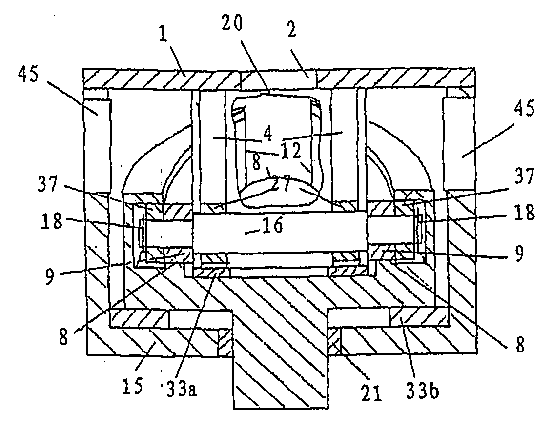
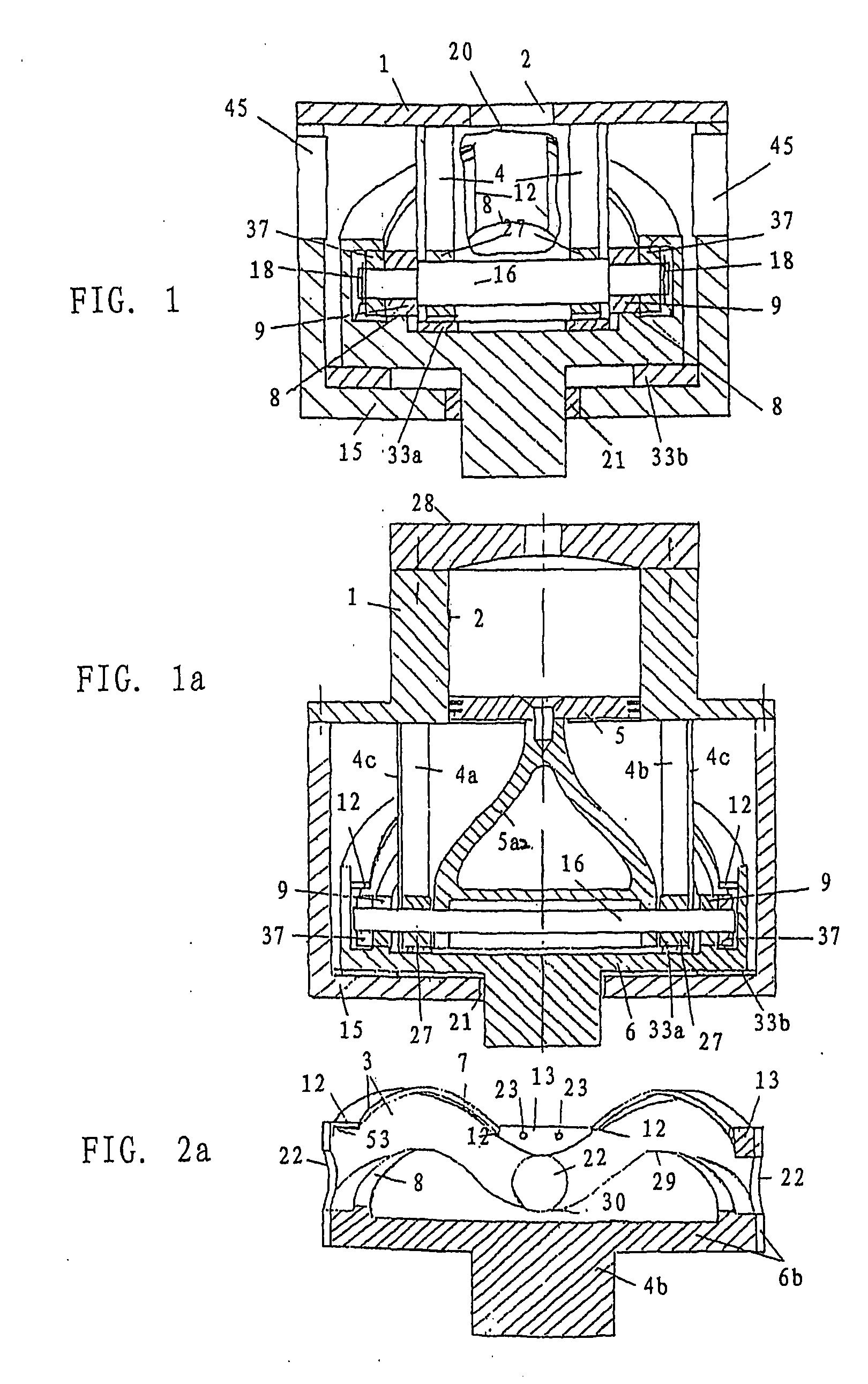
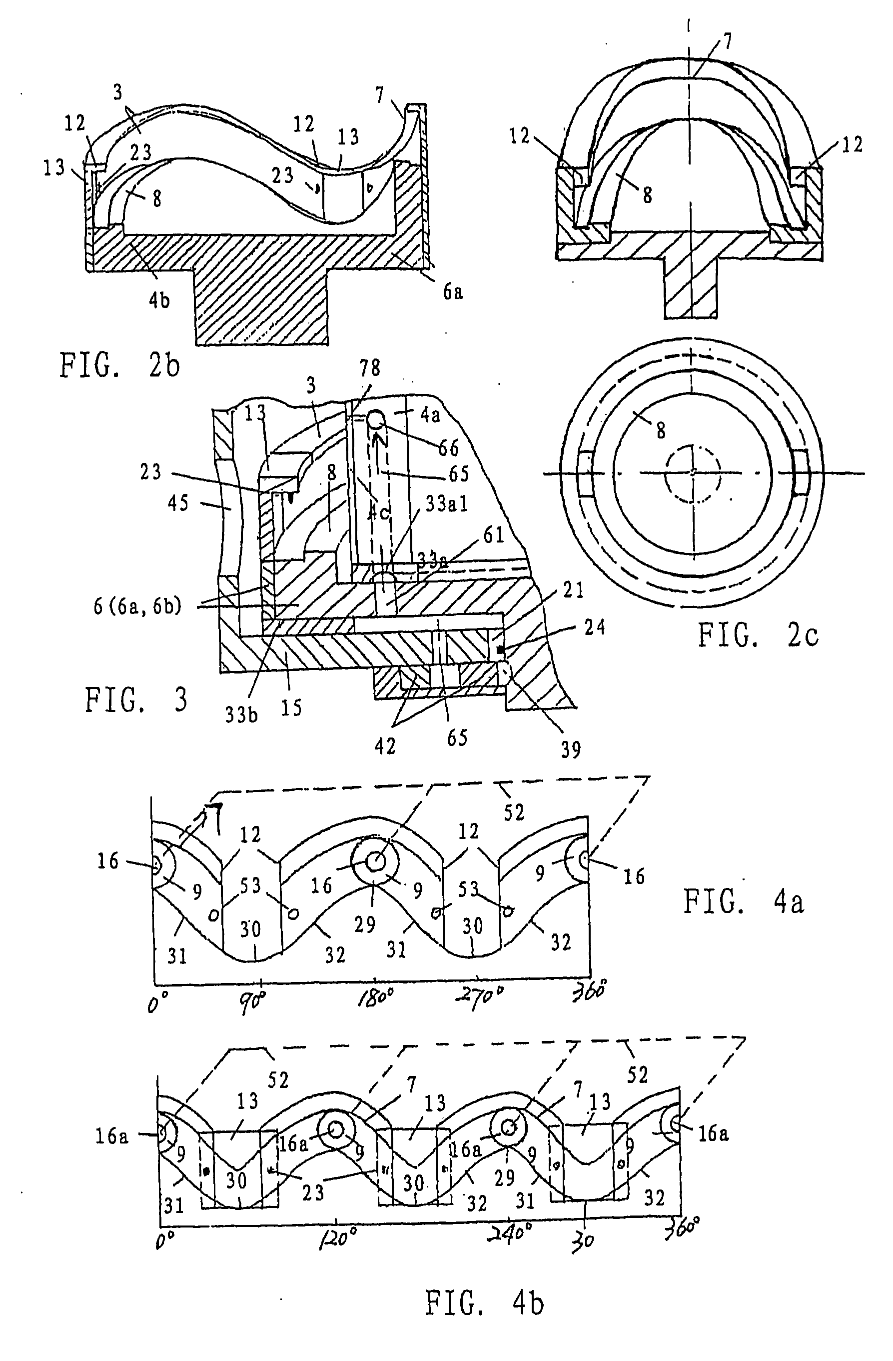
[0084] A single-cylinder and four-stroke internal combustion engine comprising a power transmission mechanism having an internal groove cam is shown in FIG. 11. The engine comprises an internal groove cam 6, a cylinder cover 28 on which a part of members forming the valve system, such as a valve and a camshaft and etc., are mounted, a cylinder 1 having a cylinder opening 2, a piston 5 and a piston rod 5a2a, two primary rollers 9, two secondary rollers 37, two guiding rollers or sliding blocks 27, a roller shaft 16, two fixed guide rails 4, a cam box 15. The internal groove cam 6 is provided in the cam box 15. The cylinder 1 having the cylinder cover 28 is fixed to the cam box 15. Two primary rollers 9 and two secondary rollers 37 are disposed near the two ends of the roller shaft at the positions corresponding to the circumferential cam contour so that they are received in the groove of the internal groove cam through two slots 12 in the upper circumferential cam contou...

Example

Embodiment 3

[0086] A double-cylinder and four stroke inline internal combustion engine comprises a power transmission mechanism having an internal groove cam. The engine comprises an internal groove cam 6 or 6b, a cylinder cover 28 on which a part of members forming the valve system, such as a valve and a camshaft and etc., are mounted, a cylinder 1 having two cylinder openings 2 disposed at the positions where one circumference 50 intersects the bi-sectors 67, two pistons 5, two piston rods 5a, two primary rollers 9, two secondary rollers 37, two guiding rollers or sliding blocks 27, a roller shaft 16, two fixed guide rails 4, a cam box 15. The internal groove cam 6 is provided in the cam box 15. The cylinder 1 having the cylinder cover 28 at the upper part thereof is fixed to the cam box 15. The lower parts of the two piston rods 5a fixed to two pistons 5 in the two cylinder openings 2 of the cylinder 1 are mounted on the roller shaft 16 so that the two pistons 5 and the roller s...


PUM


Abstract

The present invention relates to a spatial cam power transmitting mechanism for the conversion between linear movement and rotary motion. Several transmitting mechanisms for the conversion between reciprocating motion of a roller shaft and rotary motion of an internal groove cam are provided, which do not have a piston and a piston bore. A roller shaft 16 is provided on a upper portion of internal groove cam 6 in a cam casing 15, and rollers are mounted to the outer end of the roller shaft. The rollers roll in a circumferential direction on the contour line of the groove of the internal groove cam 6. At the position of fixed rails 4 opposing to the roller shaft 16, guiding rollers or slide blocks 27 are provided, wherein the fixed rails 4 are provided axially in a lower portion of a cover 1 of the cam casing. The guiding rollers or slide blocks 27 can move up and down respectively in the fixed rails. The power transmitting mechanism is used in an internal combustion engines burning petrol, diesel oil or gas, a stirling engine, a motive engine, such as air or liquid motor, a pump transmitting gas and liquid, a compressor, or other fields which need movement translation.

Description

TECHNICAL FIELD OF THE INVENTION [0001] The present invention relates to a transmission mechanism for conversion between linear movements and rotary motions, more particularly, to a transmission mechanism for conversion between the reciprocating motion of a roller shaft and the rotary motion of an internal groove cam, furthermore particularly, to a power transmission mechanism for conversion between the reciprocating motion of a piston and a rotary motion of an internal groove cam. BACKGROUND OF THE ART [0002] Chinese Patent Application No. 94100421.x, entitled “Internal Combustion Engine having Cam Piston” and published on Dec. 28, 1994, discloses a pin shaft (roller shaft) comprising a suspension beam having a free end received in an internal groove of a cam, which must be provided with a piston in order to balance the other end of the beam, as shown in FIGS. 1, 4 and 5. Therefore, the piston exerts a lateral force to the cylinder, which deteriorates the service life of the piston...

Claims


Application Information

Patent Timeline
IPC IPC(8): F16H21/16F02B23/00F02B75/16
CPCF01B9/04F16H25/125F01B9/06
Inventor ZHAO, QUM
Owner XIAMEN TUXIAN ENERGETIC SCI & TECH
Why Eureka
Try Eureka