
Production of Ferronickel

a production method and technology of ferronickel, applied in the direction of improving process efficiency, etc., can solve the problems of low grade ores and transition ores in some deposits being rejected as waste, processing routes too expensive for these ores, and total treated ore quality, etc., to achieve the effect of reducing sulfur levels and being easy to handl

Inactive Publication Date: 2008-01-17
BHP BILLITON SSM TECH PTY LTD
View PDF4 Cites 17 Cited by
  • Summary
  • Abstract
  • Description
  • Claims
  • Application Information

AI Technical Summary

Benefits of technology

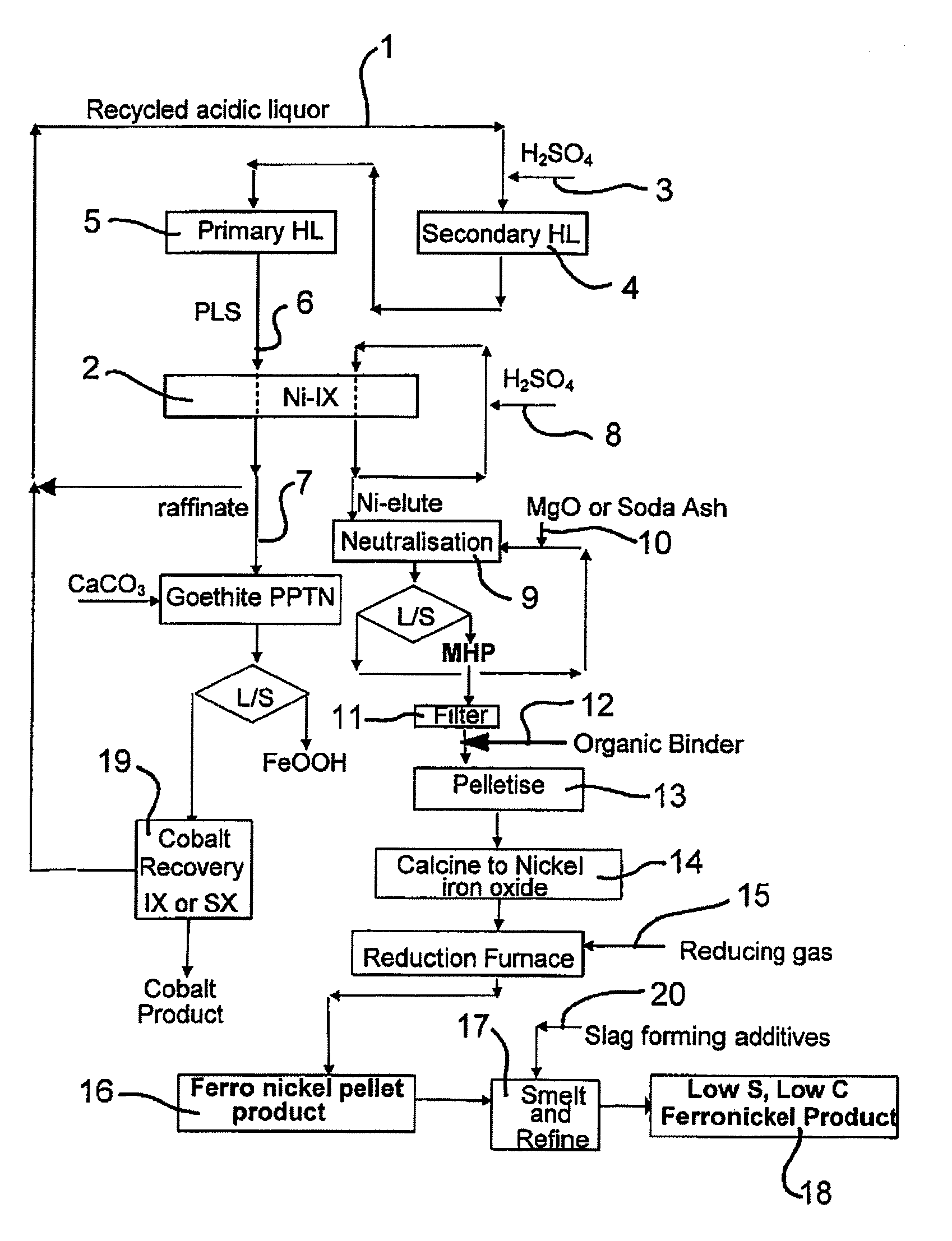
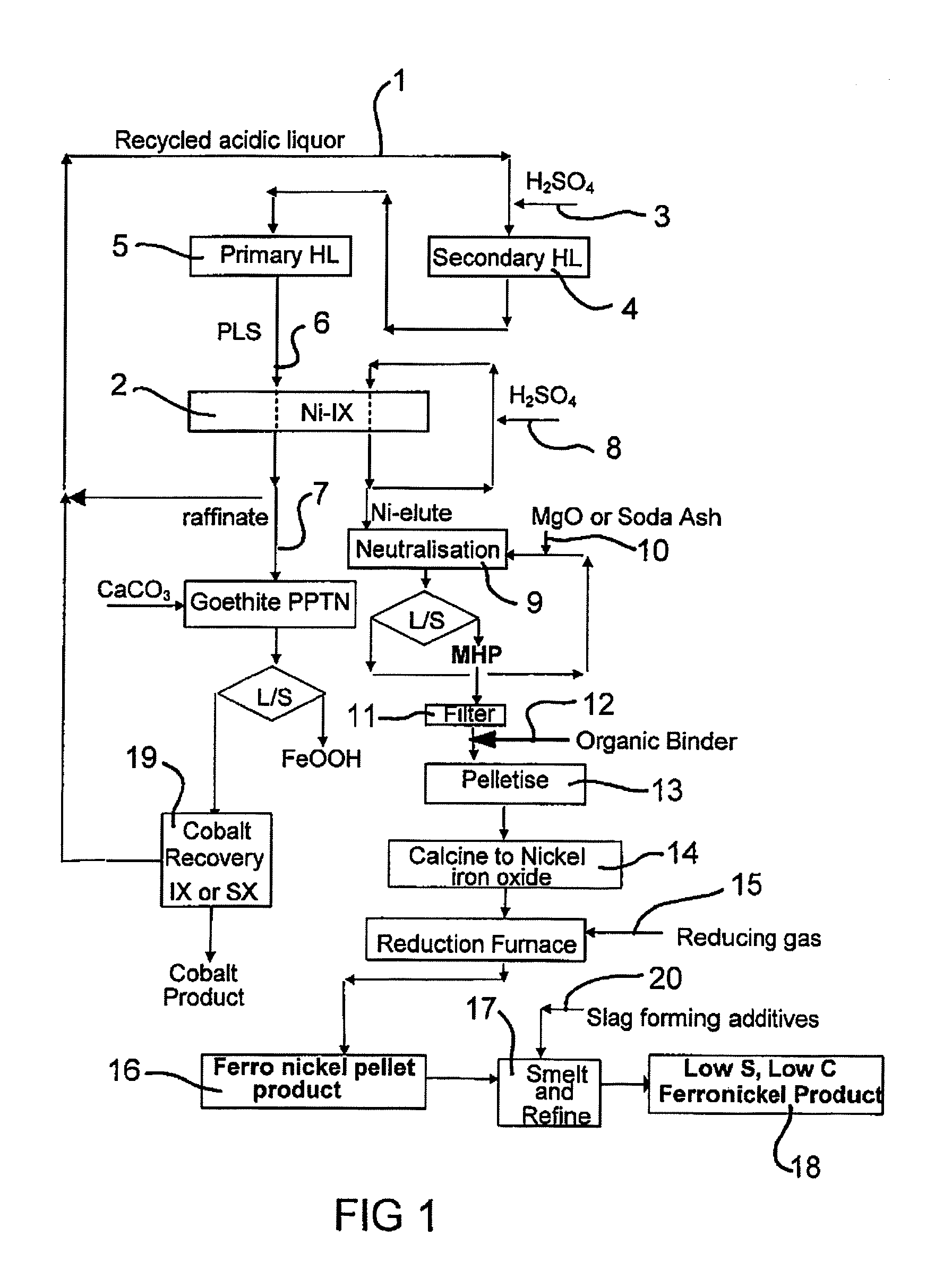
[0019] Most preferably, the acid used to strip the nickel and iron from the resin is sulfuric acid, to produce a nickel and iron loaded eluate. However, in yet a further embodiment, hydrochloric acid could be used rather than sulfuric acid to strip the nickel and iron from the resin. This will have the potential advantage in that the eluate can be neutralised with lower levels of sulfur present than would occur if sulfuric acid was used, resulting in lower levels of sulfur in the resultant mixed nickel iron hydroxide product. Therefore, depending on the levels of sulfur present, calcination can occur at a lower temperature prior to the reduction step.
[0020] The mixed nickel iron hydroxide product recovered from the ion exchange eluate is suitable for processing to the ferronickel pellets in accordance with the process of the invention. The mixed nickel iron hydroxide product would generally be in the form of a wet cake and in order to pelletise the mixed nickel iron hydroxide product, it is preferred that the wet cake is dried and pelletised with an organic binding material and water. This makes the nickel iron hydroxide pellet harder and easier to handle. The nickel iron hydroxide pellets range in size between 5 mm and 20 mm in diameter before calcination.

Problems solved by technology

This leads to the lower grade ores and transition ores in some deposits being rejected as waste.
The power requirements and high iron to nickel ore ratio for the lower nickel content limonite, saprolite, and limonite / saprolite blends in the transition zone make this processing route too expensive for these ores.
The above processes generally require “whole ore” processing as there is no effective method to beneficiate the ore.
This has the disadvantage that the mineralogical fractions of the ore which may contain lower metal values effectively dilute the total treated ore quality and increase recovery costs.
This is a highly energy intensive process as the ratio of total ore to nickel is typically forty to one, and most of the power is expended in melting slag.
It also has the disadvantage that financial value of any cobalt in the ore, which reports to the ferronickel, is not realised.

Method used


Image

  • Production of Ferronickel
  • Production of Ferronickel
  • Production of Ferronickel

Examples


example 1

Single Column Leaching with Sulfuric Acid Only

[0062] To simulate heap leaching with sulfuric acid only, 65.6 kg saprolite ore with moisture content of 20.1% was agglomerated with 98% sulfuric acid to pelletise the material with particle size of 3.35 mm to 25.4 mm. The acid dose for agglomeration was 20 kg per tonne of dry ore. The column size was 15 cm diameter×262 cm height. Sulfuric acid solution with acidity of 50 g / L was fed to column with the flux of 40 Litre / (hr.m2). The nickel extraction was 94% after 52 days. Table 3 summarizes the results.

TABLE 3Column Leaching Results with Sulfuric Acid onlyWeightkgAl %Co %Cr %Fe %Mg %Mn %Ni %Feed52.50.8120.0330.5311.016.00.1742.21oreResidue30.30.9200.0000.684.775.580.040.24Extraction %34.6110025.9674.9779.8786.7393.73

example 2

Single Column Leaching Fed with a Limonite Acid Leachate

[0063] To simulate heap leaching with acidic, nickel and cobalt containing solution e.g. pressure acid leaching PAL) or atmospheric acid leaching (AAL), 80.4 kg saprolite ore with moisture of 24.0% was agglomerated with 98% sulfuric acid to make the pellets with particle size of 3.35 mm to 25.4 mm. The acid dose for agglomeration was 25 kg per tonne of dry ore. The column size was 15 cm diameter×386 cm height. The acidic leachate from a limonite pressure leach containing nickel, cobalt and iron in solution, was fed to the column with a flux of 10 Litre / (hr.m2). The composition of this feed solution is shown in Table 4. The nickel extraction was 76% at 197 days. Table 5 summarizes the results.

TABLE 4Composition of limonite acid leachateAcidityAlCoCr(VI)FeMgMnNig / Lmg / Lmg / Lmg / Lmg / Lmg / Lmg / Lmg / L30-4045507303503450475039908550

[0064]

TABLE 5Column Leaching Results with Acidic leachateWeightkgAl %Co %Cr %Fe %Mg %Mn %Ni %Feed ore61.11...

examples 3

Counter-Current Leaching

[0065] In order to simulate the counter current leaching process, a group of counter-current column leaches were carried out with a constant acid consumption of 670 kg H2SO4 / t ore. The group contains five columns named as A, B, C, D and E. Column A was firstly fed with acidic intermediate product liquor solution (IPLS) obtained from previous column leaching (simulating the secondary leach effluent liquor) to simulate primary leaching, then fed with blank sulfuric solution of 100 g / l H2SO4 to simulate secondary leaching, and finally rinsed with pH 2 dilute H2SO4 solution. The Product liquor solution from the primary leaching was stored for nickel recovery with IX. The IPLS from the secondary leaching and rinsing was used as feed solution to column B as primary leaching and so-on. Only the results of column B, C, D and E are quoted because these columns had the same initial conditions. The operation time of each column was about 30 days.

[0066] 26 kg saprolite...


PUM

PropertyMeasurementUnit
Temperatureaaaaaaaaaa

Abstract

A process for producing a ferronickel product from a mixed nickel iron hydroxide product, said process including the steps of: providing a mixed nickel iron hydroxide product; pelletising the mixed nickel iron hydroxide product to produce nickel iron hydroxide pellets; calcining the nickel iron hydroxide pellets to produce mixed nickel iron oxide pellets; and reducing the nickel iron oxide pellets with one or more reducing gases at high temperatures to produce ferronickel pellets.

Description

[0001] This application is a continuation of and claims priority from PCT / AU2006 / 000225 published in English on Aug. 31, 2006 as WO 2006 / 089358 and from AU 2005900852 filed Feb. 24, 2005, the entire contents of each are incorporated herein by reference.FIELD OF THE INVENTION [0002] In general, the present invention relates to a new method for producing ferronickel from mixed nickel iron hydroxide by a combination of pelletisation, calcination and reduction. In particular, the present invention provides a new method which involves pelletisation of nickel iron hydroxide, calcination of the pellets to produce porous pellets of nickel iron oxide, and reduction to produce a novel ferronickel product. The ferronickel product may be further smelted to make a high quality ferronickel product. The method is particularly suited to nickel iron hydroxide precipitate that can be produced from an acidic product liquor derived from nickel containing ore bodies by a process such as pressure acid le...

Claims


Application Information

Patent Timeline
IPC IPC(8): C22C38/08C21B15/00
CPCC21B15/00C22B1/244C22B23/0453C22B5/12C22B23/023C22B3/42Y02P10/20C22B1/02C22B23/00
Inventor DUARTE, ALEXEYLIU, HOUYUANRATCHEV, IVAN PETKOV
Owner BHP BILLITON SSM TECH PTY LTD
Learn More