Water purification and treatment apparatus and treatment process using the apparatus

a technology of water purification and treatment apparatus, applied in the direction of multi-stage water/sewage treatment, liquid displacement, separation process, etc., can solve the problems of increasing disposal costs, limited water purification efficiency, and conventional activated sludge aeration basins cannot provide sufficient dissolved oxygen amount, etc., to achieve the effect of big treatment capacity

Inactive Publication Date: 2008-01-17
CHENG JIAN RUNG +1
View PDF18 Cites 17 Cited by
  • Summary
  • Abstract
  • Description
  • Claims
  • Application Information

AI Technical Summary

Benefits of technology

[0011]A primary objective of the present invention is to provide a water purification and treatment apparatus, by which the water purification and treatment can be performed rapidly, the capacity of treatment is big, the sludge generated duration operation is less and can be used as organic fertilizer directly, at the same time, a wide range of kinds of water sources can be treated.

Problems solved by technology

Over a long time of treatment, large amounts of chemicals will be consumed, at the same time, more sludge will be produced and may be noxious due to residual chemicals contained therein, which thereby can not be utilized directly as organic fertilizer, and also is not suitable to be buried directly, but should be further disposed, resulting in the increase of disposal costs.
Further, the efficiency of water purification is limited by using the above processes.
But, a conventional activated sludge aeration basin can not provide sufficient dissolved oxygen amount because the sludge will be restricted in limited aeration time and space duration its treatment, especially as large amounts of microorganisms propagate in the water and consume much dissolved oxygen in the water.
Therefore, if aeration amount in unit time and temperature control are not operated appropriately, many microorganisms will die rapidly.
It is not suitable for treating lots of sewage and wastewater.
But, when much more sewage and wastewater is treated, the sludge amount generated is still very annoying and need to be further reduced in volume.
Treatment scale will be somewhat limited.
In addition, due to influence of industrial wastewater and polluted air, the saw water also contains much heavy metal therein.
Therefore, even though the raw water is ocean water, besides salts contained therein, the concentration of mercury and lead is also high, and those can not be removed by the reverse osmosis process over a long time of period.
Therefore, the sludge around the discharging outlet may be unable to be discharged out successfully, but settled and accumulated there gradually.
The apparatus also has the disadvantages of short life time, high maintenance costs and uneconomic.
As to a conventional square basin having a sludge scrapping device, the device operates reciprocally, therefore each sludge scrapping cycle has an idle stoke of wasted time.
Therefore, in summarization of the above apparatuses, they all has the disadvantages of short life time, high maintenance costs and uneconomic.

Method used


Image

  • Water purification and treatment apparatus and treatment process using the apparatus
  • Water purification and treatment apparatus and treatment process using the apparatus
  • Water purification and treatment apparatus and treatment process using the apparatus

Examples


first embodiment

Seawater Desalinating Device

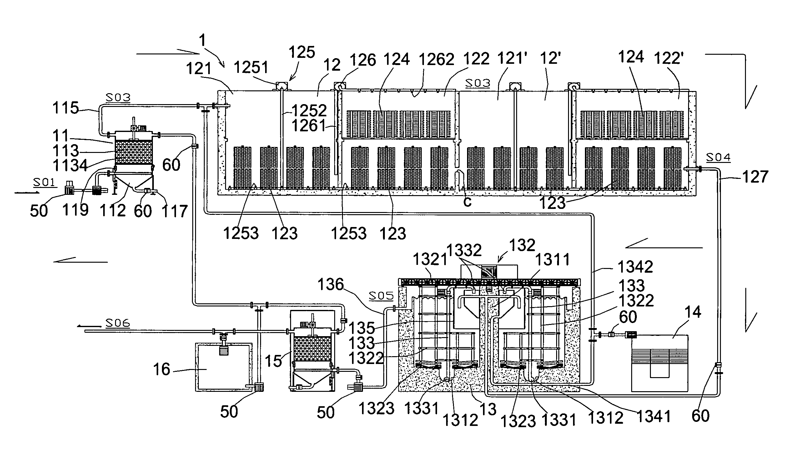
[0099]FIG. 3 shows a seawater desalination device in accordance with the present invention. The seawater desalination device 1 comprises a first filter, a first contact aeration basin 12 and a second contact aeration basin 12′, a settling basin 13, a sludge dehydrator 14, and a second filter 15 and a reverse cleaning water container 16.

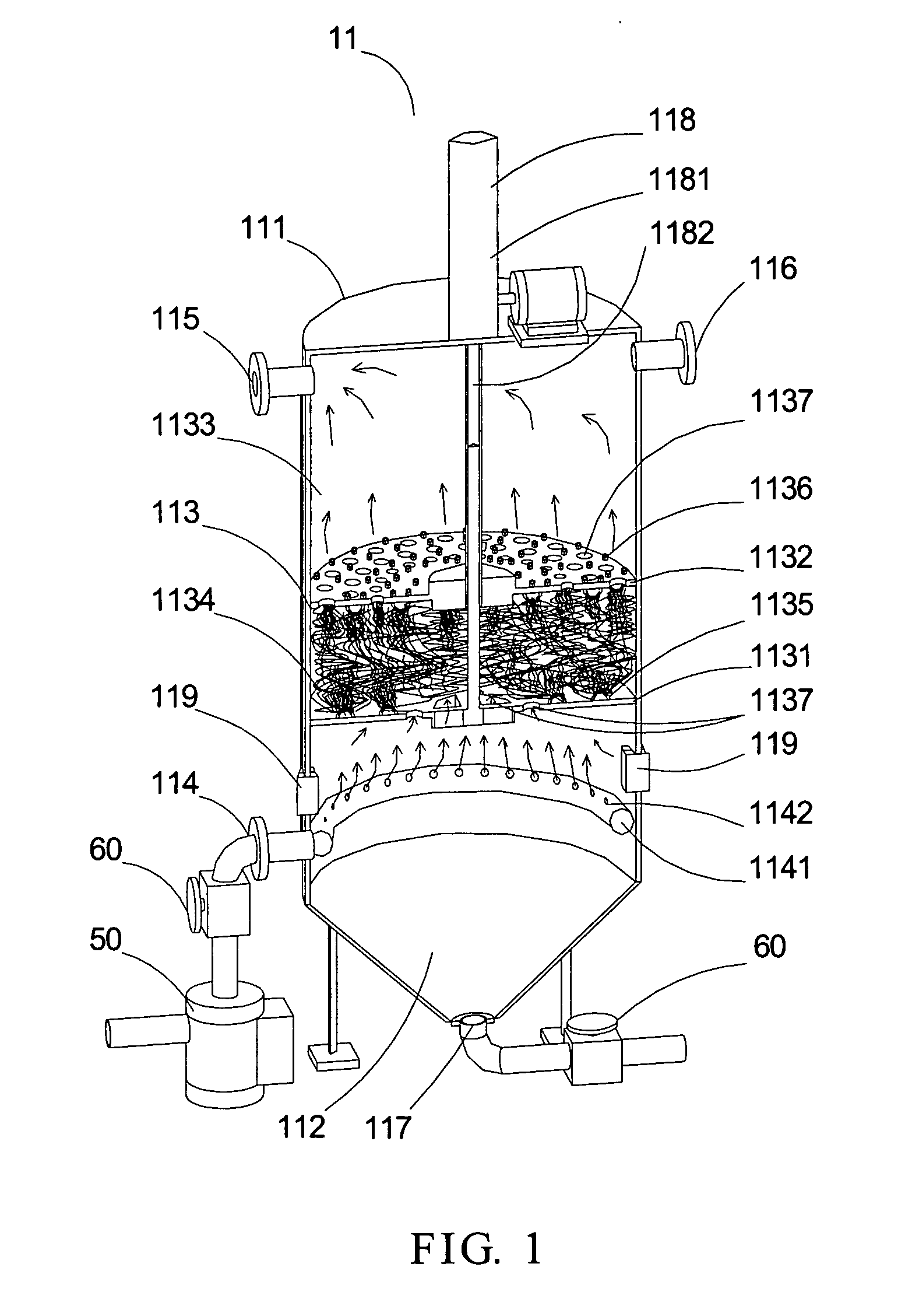
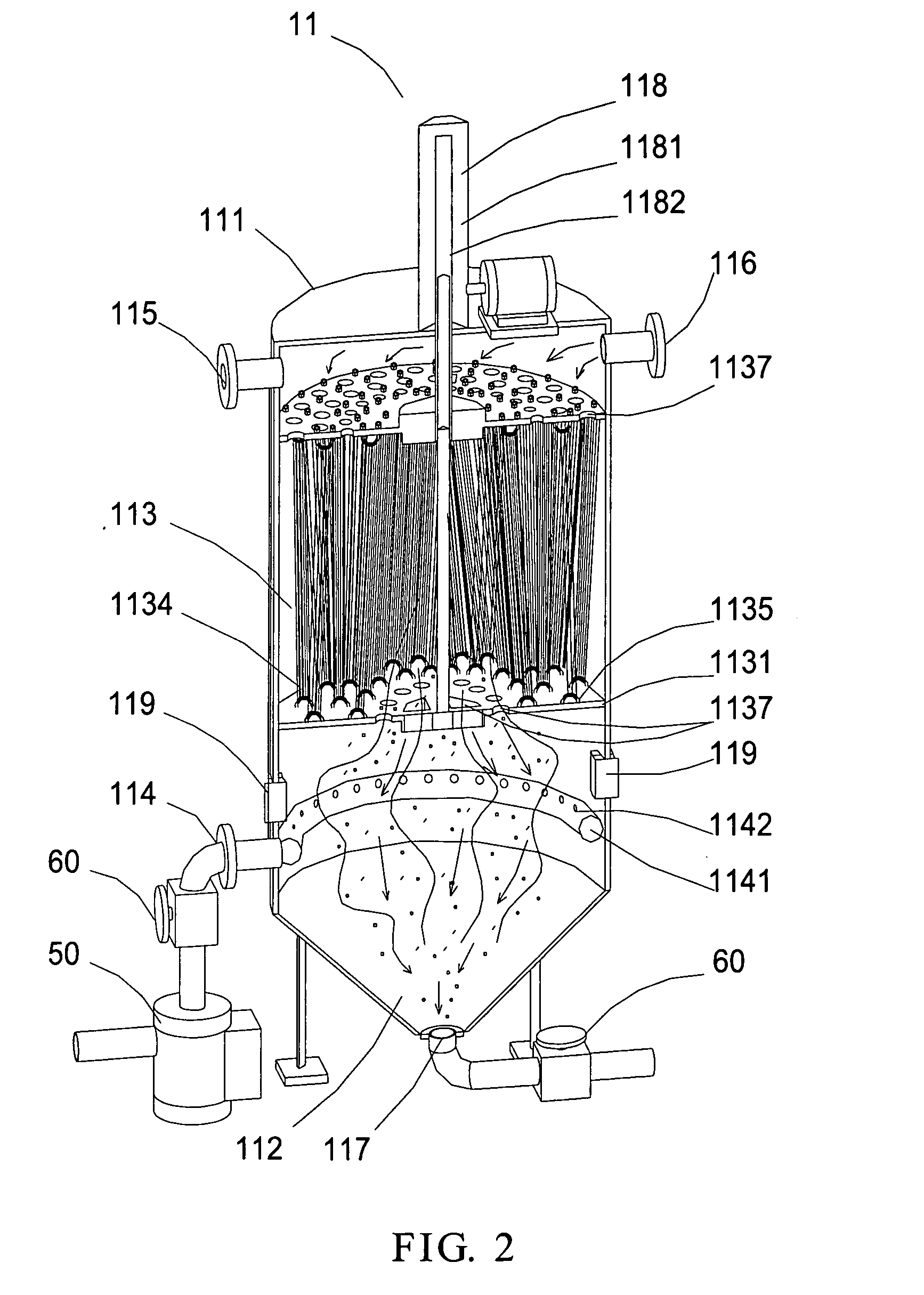
[0100]As shown in FIG. 1, the filter of the present invention is mainly composed of a body base 111, a hopper base 112, a filtering tank 113, a primary inlet and outlet pipes, a pump 50, and an oil hydraulic press 118. The hopper base 112 and the elongate barrel filtering tank 113 both connect with the primary inlet pipe 114, and suction water by the pump 50. The primary inlet pipe 114 connects with and extends into the hopper base 112, and forms a ring pipe 1141 on the hopper base 112 which has a plurality of water outlets 1142 on the upper part thereof, allows water to enter into the filtering tank 113 uniformly. Sludge c...

second embodiment

Sewage and Wastewater Purification Device

[0115]FIG. 5 is a schematic view showing a sewage and wastewater purification and treatment device in accordance with the present invention. As shown in FIG. 5, the sewage purification and treatment device 2 uses a barrier 21 in place of the first filter 11 in the seawater desalination device 1, and other components thereof are identical. The reference numerals of the assemblies of the settling basin in FIG. 5 are the same with those in FIG. 3.

[0116]In this embodiment, when the water source to be treated is domestic sewage, the sewage is fed to the front aeration tank 221 of the first contact aeration basin 22 through the water discharging pipe 211, after medium and big foreign materials and greases in the sewage are blocked by the barrier 21, and then the subsequent treatment processes are identical to those in the first embodiment.

[0117]Testing results of water quality taken in each treatment stage after treated by the present sewage and wa...


PUM

PropertyMeasurementUnit
pore sizeaaaaaaaaaa
temperatureaaaaaaaaaa
volumeaaaaaaaaaa

Abstract

The present invention provides a water purification and treatment apparatus using a combination of sedimentation, filtration, and bio-contact aeration processes, which comprises at least one rapid water purification filter having a hopper base for settled sludge and a filtering tank; at least one cylindrical settling basin for sedimentation and filtration; and at least one aeration basin having an under water and an over water bio-film contact parts, for rapidly filtering raw water or wastewater contacted with bio-contact aeration, and performing water purification and treatment.

Description

BACKGROUND OF THE INVENTION[0001]1. Field of the Invention[0002]The present invention relates generally to a water purification and treatment apparatus, and in particular to a water purification and treatment apparatus and a water purification and treatment process using a combination of sedimentation, filtration, and bio-contact aeration processes.[0003]2. The Prior Arts[0004]The purpose of purifying and treating raw water, sewage or wastewater is, in general, to improve water quality to reach the standard for fresh drinking, or the standard for discharging. As to the former, a reverse osmosis process is commonly used no matter what is the source of water to be purified, which may be, for example, seawater, river water, well water or rainwater. As to the latter, based on the source of sewage or wastewater to be purified, an anaerobic chemical treatment process, an aerobic activated sludge process, a bio-contact aeration process and the like, or a combination thereof may be used to ...

Claims


Application Information

Patent Timeline
Patent Type & Authority Applications(United States)
IPC IPC(8): C02F3/02
CPCC02F3/06C02F3/04Y02W10/10
Inventor CHENG, JIAN-RUNGHSIAO, TONG-FU
Owner CHENG JIAN RUNG
Why Eureka
Try Eureka