Method and apparatus for transferring an array of oriented carbon nanotubes

a carbon nanotube and array technology, applied in the field of nanotechnology, can solve the problems of not being able to grow nanotubes by acetylene-based cvd process on metals, unable to grow patterned aligned mwnts on any type of substrate, and unable to achieve high-efficiency growth.

Inactive Publication Date: 2008-01-17
BOARD OF RGT THE UNIV OF TEXAS SYST
View PDF7 Cites 26 Cited by
  • Summary
  • Abstract
  • Description
  • Claims
  • Application Information

AI Technical Summary

Benefits of technology

[0010] The present invention transfers arrays and patterned arrays of aligned multiwalled carbon nanotubes under high electric field in a high vacuum from one surface to another. Such a transfer of matter in high vacuum over macroscopic distances and subsequent deposition on surfaces while still retaining the pattern and orientation without using mask and pre-patterned substrate was heretofore unknown. Note that the matter transfer described herein is not merely the transfer of single ions or molecules, but is the transfer of nano size structures made of huge number of atoms. Such sublimation is accompanied by field electron emission and spark

Problems solved by technology

This method, however, has a serious drawback: aligned MWNTs can only be grown only on certain materials because of the high temperature at which the growth takes place (about 700° C.).
As a result, current technology does not allow patterned aligned MWNT to be grown on any type of substrate.
For example, it is not possible to grow nanotubes by an acetylene-based CVD process on metals that have low melting temperatures (e.g., Al, Pb, etc.) or metals that react with acetylene (e.g., Cu, etc.).
MWNTs produced in this manner have limited application because of the weak adhesion of the carbon powder to the substrate.
The application of this method is hindered because the printable field emitters produced by this method have high thresho

Method used


Image

  • Method and apparatus for transferring an array of oriented carbon nanotubes
  • Method and apparatus for transferring an array of oriented carbon nanotubes
  • Method and apparatus for transferring an array of oriented carbon nanotubes

Examples


example 1

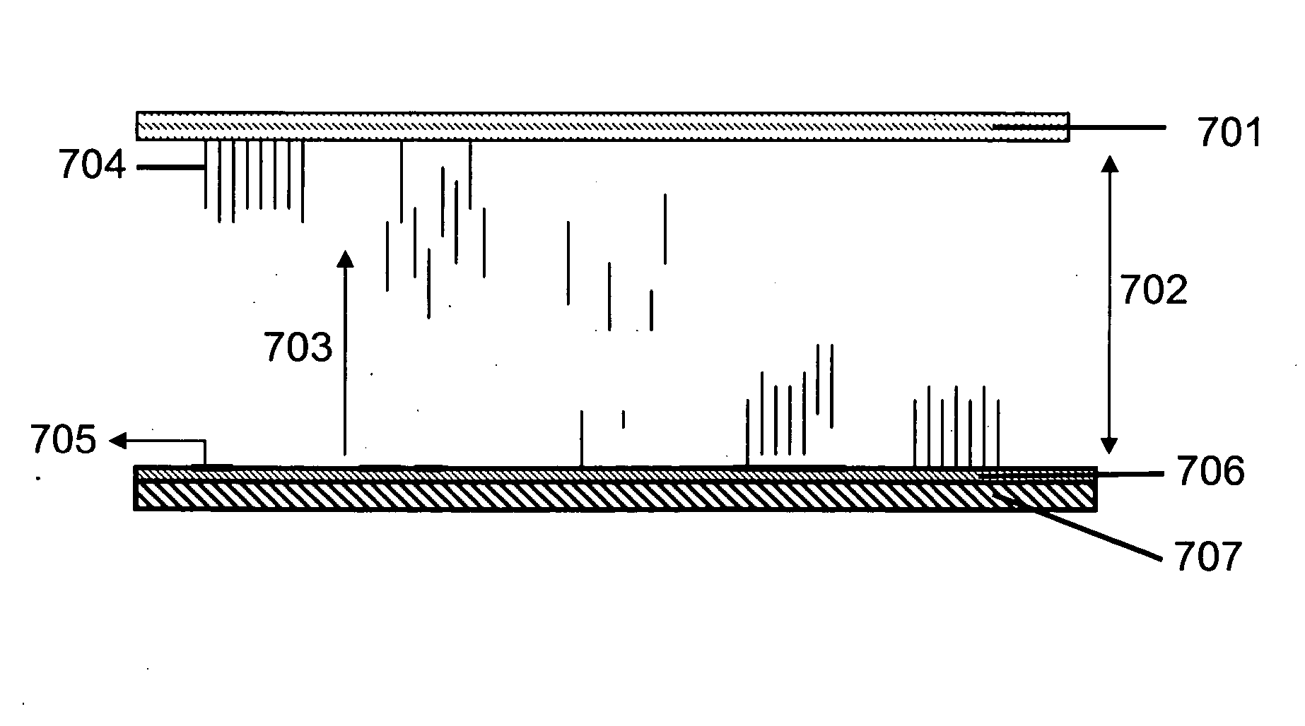
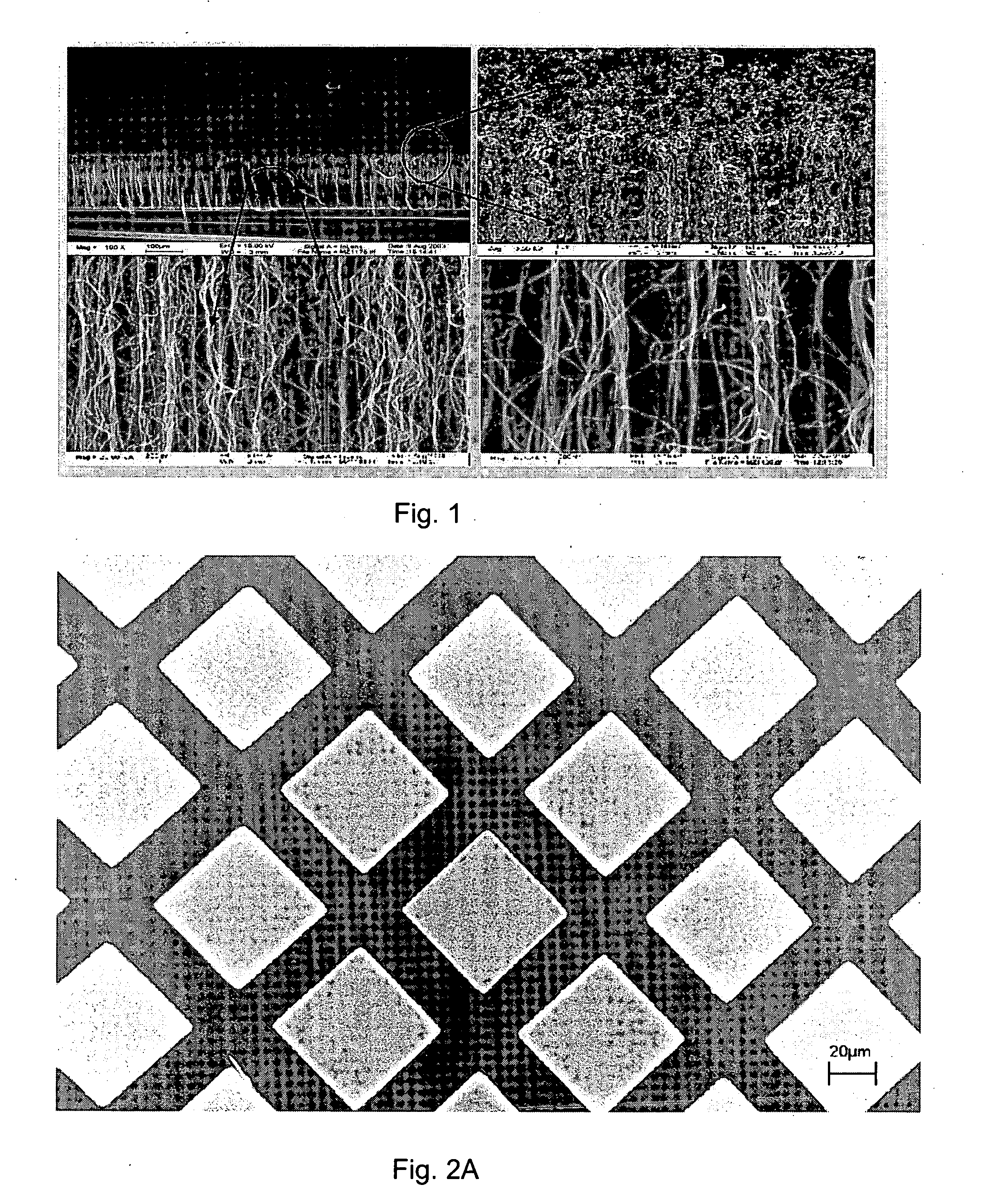
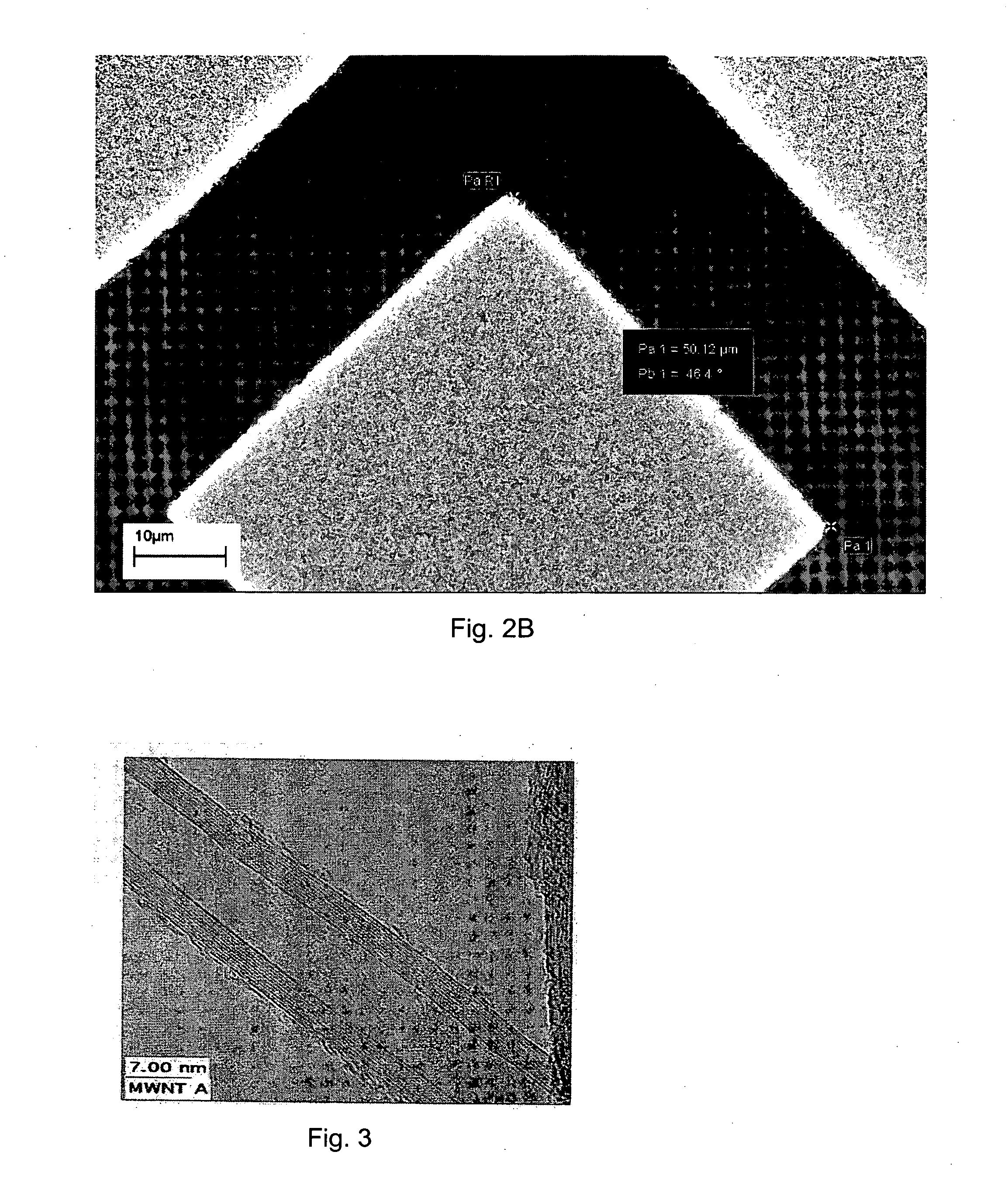
[0095] Growth process of vertically aligned forests of multi walled carbon nanotubes. The well-ordered aligned MWNTs were synthesized by the catalytic thermal chemical vapor deposition (CVD) at the atmospheric pressure. The substrates were n++ Silicon (Si) (100) wafers with a resistivity of 0.005-ohm cm. A 5 nm thick Iron (Fe) film was deposited on the Si wafers by electron beam evaporation or photolithography using a lift-off process. The Fe deposited substrates were placed in the center of a quartz tube (I.D. 45 mm) located in a horizontal tubular electric furnace. The temperature of the substrates was raised at a rate of 15° C. / min in a Helium atmosphere. Helium gas of 550 sccm flowed into the quartz tube while the furnace was heated in order to prevent the oxidation of transition metal. After reaching the reaction temperature 680° C., Acetylene gas was introduced into the chamber at the flow rate of 40 sccm. The deposition time was varied from 3 min to 12 min. The length of the ...

example 2

[0096] Growth of vertically aligned and patterned carbon multi walled nanotubes. In order to grow patterned multi walled carbon nanotubes, the Fe catalyst film deposited on the on the Si substrate was patterned using e-beam photolithography. The size of the pattern could be changed as necessary. The transfer in the case of patterned nanotubes is similar to that of unpatterned aligned nanotubes.

example 3

[0097] Deposition on metallic surfaces. The transfer of the nanotubes can be achieved onto surfaces of conductive materials such as Al or Cu. Since the transfer takes place when the nanotube tips are very hot, they penetrate into the metal surface and lead to a better electrical contact.


PUM


Abstract

The present invention provides a method and apparatus for transferring an array of oriented carbon nanotubes from a first surface to a second surface by providing the array of oriented carbon nanotubes on the first surface within a vacuum chamber, providing the second surface within the vacuum chamber separate from the first surface, and applying an electric potential between the first surface and the second surface such that the array of oriented carbon nanotubes are sublimed from the first surface and re-deposited on the second surface.

Description

REFERENCE TO RELATED APPLICATIONS [0001] This application claims priority to U.S. Provisional Patent Application No. 60 / 626,789 filed Nov. 11, 2004 entitled Method and Apparatus for Transferring an Array of Oriented Carbon Nanotubes, which is herein incorporated by reference in its entirety.U.S. GOVERNMENT RIGHTS [0002] The U.S. Government may own certain rights in this invention pursuant to the terms of the U.S. Air Force Office of Scientific Research Grant No. F 49620-03-1-0164.FIELD OF THE INVENTION [0003] The present invention relates generally to the field of nanotechnology and, more particularly, to a method and apparatus for transferring an array of oriented carbon nanotubes. BACKGROUND OF THE INVENTION [0004] Aligned multiwalled carbon nanotubes (MWNT) are most commonly grown using chemical vapor deposition (CVD). This method, however, has a serious drawback: aligned MWNTs can only be grown only on certain materials because of the high temperature at which the growth takes p...

Claims


Application Information

Patent Timeline
IPC IPC(8): B32B9/00
CPCB81C1/00111Y10T428/30Y10S977/89H01J9/025
Inventor ZAKHIDOV, ANVAR A.NANJUNDASWAMY, RASHMILI, SERGEYZAKHIDOV, ALEXANDERZHANG, MEIBAUGHMAN, RAY H.
Owner BOARD OF RGT THE UNIV OF TEXAS SYST
Why Eureka
Try Eureka