Insulating magnectic metal particles and method for manufacturing insulating magnetic material

Active Publication Date: 2008-02-07
KK TOSHIBA
View PDF13 Cites 105 Cited by
  • Summary
  • Abstract
  • Description
  • Claims
  • Application Information

AI Technical Summary

Problems solved by technology

For example, in an antenna device indispensable for portable communication terminals, the electromagnetic radiation emitted from the antenna cause a transmission loss in the course of transmission.
The transmission loss is consumed as a thermal energy in electronic parts and printed circuit boards, whereby it becomes a cause for generating heat in the electronic parts.
As a consequence, the radio signal to be transmitted to the outside is cancelled, so that it is necessary to transmit an excessive high-power radio signal, resulting in a setback for effective utilization of electric power.
Because of this, it is compelled to include an unnecessary space, and as a result, it is difficult to intend realization of space saving.
However, since a transmission loss increases due to a dielectric loss in a dielectric material, transmission and reception sensitivity cannot be obtained so that such an antenna device is applied as an auxiliary antenna device in the actual situation.
Thus, there is a limitation in electric power saving.
However, a metal or an alloy is used in a usual high relative magnetic permeability material, so that when the frequency of electromagnetic radiation increases, a transmission loss due to eddy currents becomes remarkable, and hence, it becomes difficult to use for an antenna substrate.
However, such an antenna device approaches a resonant frequency

Method used


Image

  • Insulating magnectic metal particles and method for manufacturing insulating magnetic material
  • Insulating magnectic metal particles and method for manufacturing insulating magnetic material

Examples


example 1-1

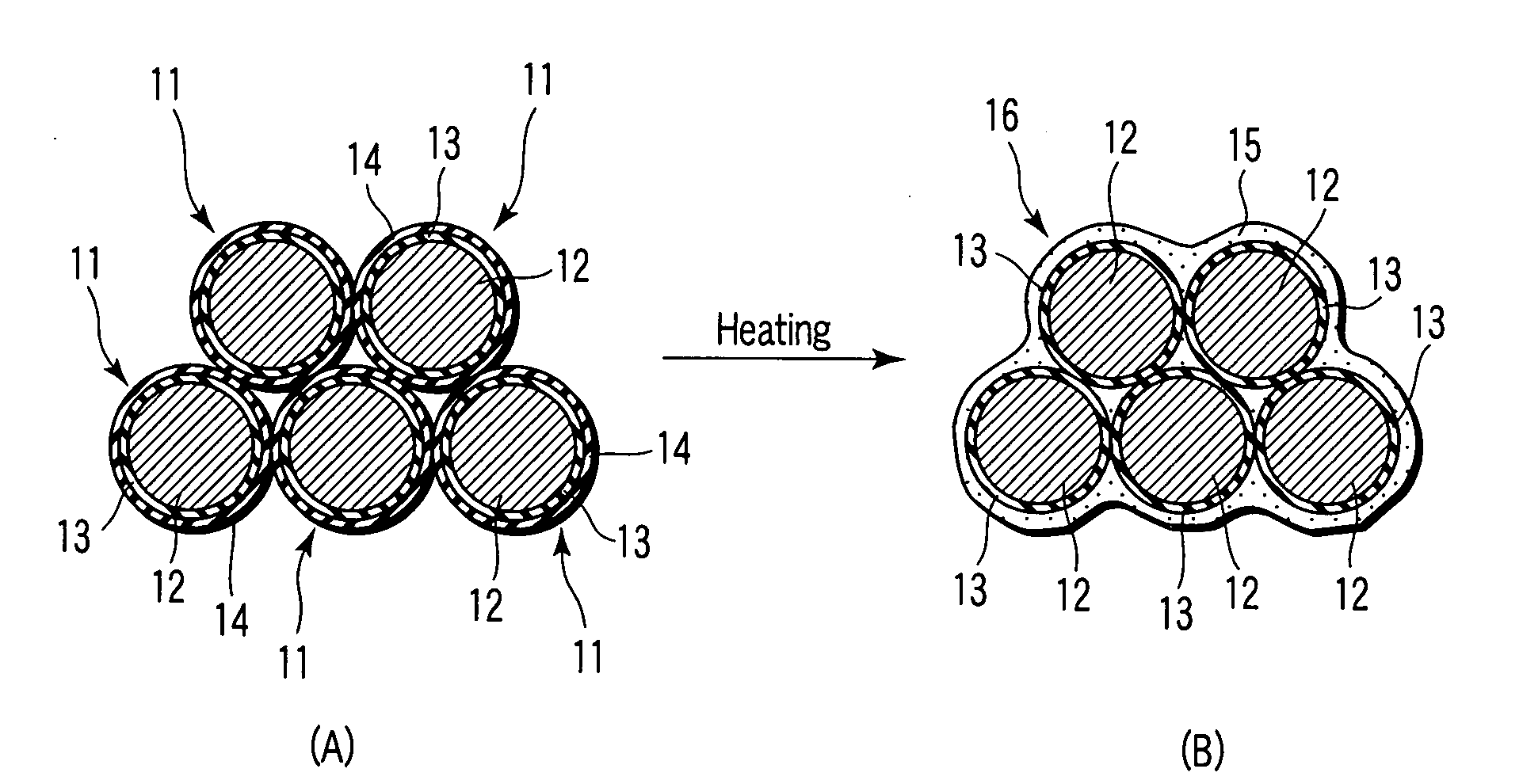
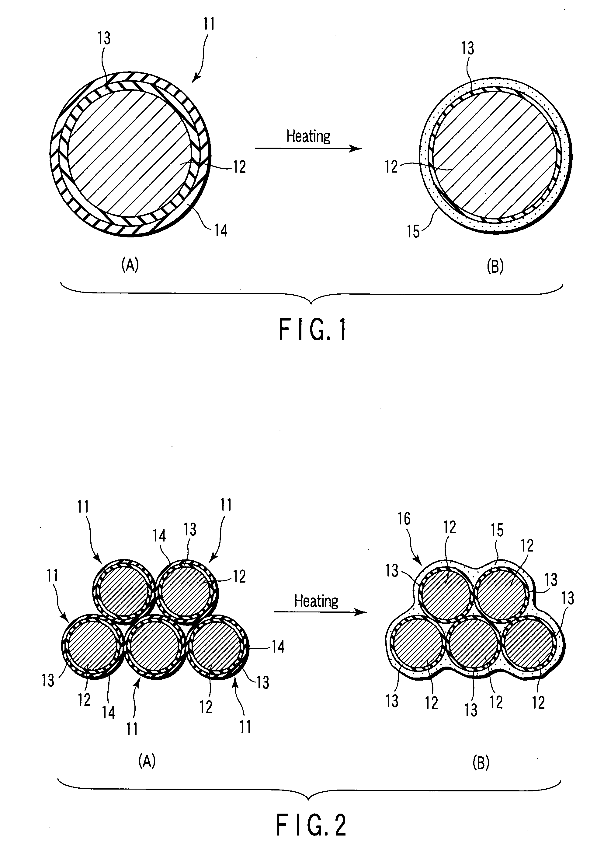
[0067]Fe particles having a particle size distribution of 20 to 70 nm were immersed into a tetraethoxysilane [Si(OC2H5)4] solution to disperse them, thereby covering the surfaces of the Fe particles were covered with a silicide, and the Fe particles were sintered at 400° C. after drying the particles to form a first inorganic insulating layer made of SiO2 and having an average thickness of 4 nm. Subsequently, the Fe particles covered with the first inorganic insulating layer were immersed into a triethylborate [B(OC2H5)3] solution to disperse them, thereby covering the surface of the first inorganic insulating layer with a boron compound, and the Fe particles covered with the boron compound were sintered at 300° C. after drying the particles to form a second inorganic insulating layer made of B2O3 and having an average thickness of 4 nm. Thus, insulating magnetic metal particles having the Fe particles covered with the first and second inorganic insulating layers were fabricated.

[00...

example 1-2

[0073]An insulating magnetic material was manufactured in the same manner as in Example 1-1 except that the same Fe particles covered with the first inorganic insulating layer as that of Example 1-1 were immersed into a tri-(tertiary amiloxy) bismuth solution to disperse them, thereby covering the surface of the first inorganic insulating layer with a bismuth compound, and the covered particles were sintered at 400° C. after drying the particles, whereby a second inorganic insulating layer made of Bi2O3 and having an average thickness of 5 nm was formed to fabricate insulating magnetic metal particles being Fe particles covered with the first and second inorganic insulating layers.

example 1-3

[0074]An insulating magnetic material was manufactured in the same manner as in Example 1-1 except that the same Fe particles covered with the first inorganic insulating layer as that of Example 1-1 were immersed into a dis-(dipivaloyl methanate) lead solution to disperse them, thereby covering the surface of the first inorganic insulating layer with a lead compound, and the covered particles were heated at 400° C. after drying the particles, whereby a second inorganic insulating layer made of PbO and having an average thickness of 4 nm was formed to fabricate insulating magnetic metal particles being Fe particles covered with the first and second inorganic insulating layers.


PUM

PropertyMeasurementUnit
Thicknessaaaaaaaaaa
Thicknessaaaaaaaaaa
Thicknessaaaaaaaaaa

Abstract

An insulating magnetic metal particle includes a magnetic metal particle containing at least one metal selected from the group consisting of Co, Fe, and Ni and having a diameter of 5 to 500 nm, a first inorganic insulating layer made of an oxide that covers the surface of the magnetic metal particle, and a second inorganic insulating layer made of an oxide that produces a eutectic crystal by reacting together with the first inorganic insulating layer at the time of heating them, the second inorganic insulating layer being coated on the first inorganic insulating layer. A thickness ratio of the second inorganic insulating layer with respect to the first inorganic insulating layer is set so that the first inorganic insulating layer remains on the surface of the magnetic metal particle after producing the eutectic crystal.

Description

CROSS-REFERENCE TO RELATED APPLICATIONS[0001]This application is based upon and claims the benefit of priority from prior Japanese Patent Application No. 2006-214813, filed Aug. 7, 2006, the entire contents of which are incorporated herein by reference.BACKGROUND OF THE INVENTION[0002]1. Field of the Invention[0003]The present invention relates to insulating magnetic metal particles, and a method for manufacturing an insulating magnetic material.[0004]2. Description of the Related Art[0005]In recent years, downsizing and weight saving of electronic communication equipment are intended with rapid increase of communicatory information. As a result, it is desired to reduce the size and the weight of electronic parts to be loaded on such equipment. In the existing portable communication terminals, most information transmission is conducted by means of transmission and reception of radio signals. A frequency band of radio signals which is applied at present is in a high-frequency region ...

Claims


Application Information

Patent Timeline
IPC IPC(8): H05K9/00B05D5/12B22F1/16
CPCB22F1/02B22F2998/00C22C2202/02H01F1/24Y10T428/12181H01F41/0246Y10T428/2991B22F1/0018B22F1/16B22F1/054
Inventor HARADA, KOUICHISUETSUNA, TOMOHIROSUENAGA, SEIICHIYONETSU, MAKI
Owner KK TOSHIBA
Why Eureka
Try Eureka