

Abnormality Diagnosing System For Mechanical Equipment
a mechanical equipment and abnormality diagnosis technology, applied in the direction of vibration measurement in solids, fluid pressure measurement by mechanical elements, frequency analysis, etc., can solve the problems of large labor cost, defect in rotary or sliding-rolling members, and large maintenance cost of apparatuses, so as to prevent noise signals, accurately detect abnormalities, and accurately diagnose abnormalities
- Summary
- Abstract
- Description
- Claims
- Application Information
AI Technical Summary
Benefits of technology
Problems solved by technology
Method used
Image

Examples
fifth embodiment
[0291]FIG. 22 is a flowchart showing the process sequence performed by an abnormality diagnosing system according to a fifth embodiment. This flowchart differs from that in FIG. 18 in that a filter process (S211) performed by a digital low-pass filter is added before the decimation process (S203). Further, the repetition count determination process (S207) and the phase shift process (S208) are not shown.
[0292] When, a band is lowered in advance by the digital low-pass filter in this manner, before the decimation process (S203), the affects of aliasing, etc., can be reduced, and a FFT operation for the low band can be stably performed. Compared with the system in FIG. 18, the program code for the digital low-pass filter and the filter coefficient calculated in consonance with the filter property are additionally required. However, this system is effective because the removal of noise is ensured. FIG. 23 shows the outer ring scratch diagnosis results obtained for the fifth embodiment...
sixth embodiment
[0293]FIG. 24 is a functional block diagram showing an abnormality diagnosing system according to a sixth embodiment.
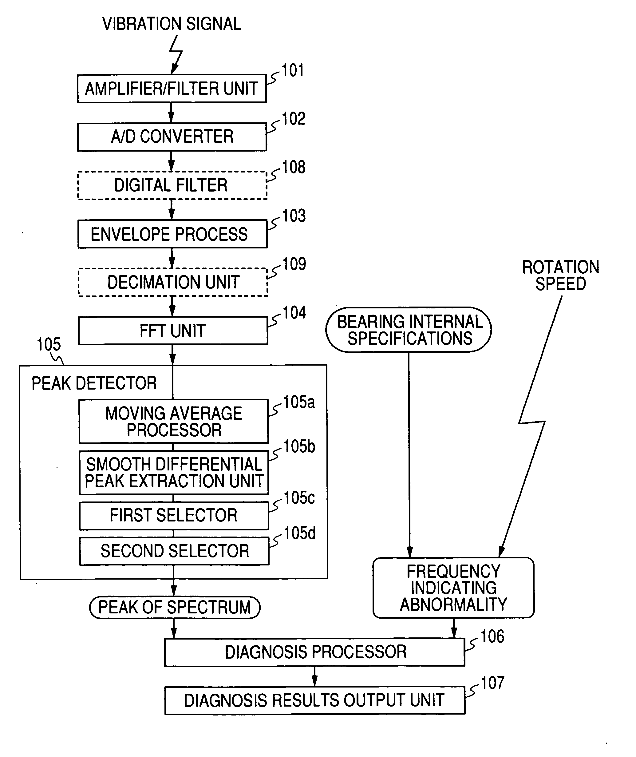
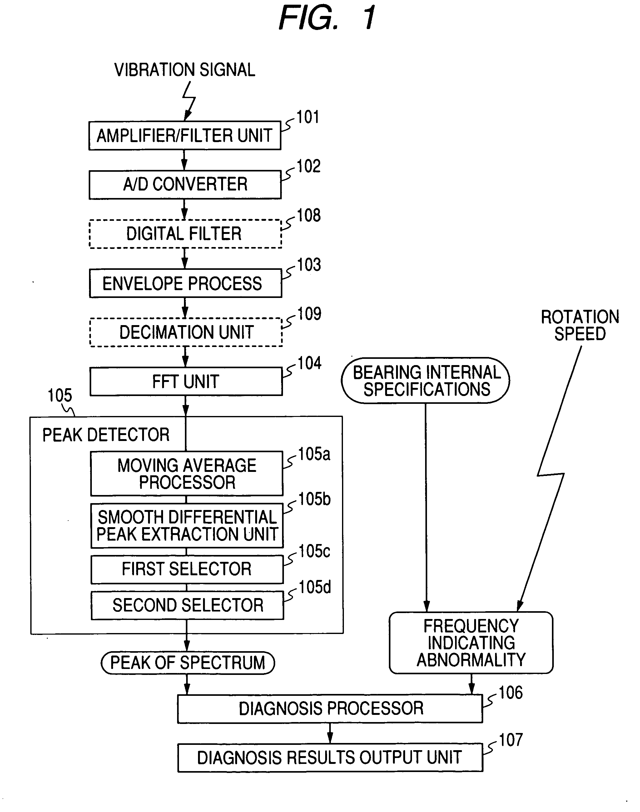
[0294] As shown in FIG. 24, the abnormality diagnosing system for the sixth embodiment includes: an analog amplifier and filter 301, an A / D converter 302, a digital filter 303, a decimation processor 304, an absolute value processor. (envelope processor) 305, a zero interpolation unit (interpolation processor) 306, a Hanning window function processor 307, a FFT unit 308, a peak detector 309, a bearing defect fundamental frequency calculator 310, a comparator 311, an integration unit 312, a diagnosis processor 313 and a diagnosis results output unit 314.
[0295] The analog amplifier and filter 301 receives a signal detected by a vibration sensor (including an acoustic sensor) 317 that detects sounds or vibrations generated by mechanical equipment to be diagnosed. The analog amplifier and filter 301 amplifies the input signal using a predetermined gain, and blocks a sig...
seventh embodiment
[0338]FIG. 28 is a schematic configuration diagram showing a railway vehicle that includes an abnormality diagnosis apparatus according to a seventh to a thirteenth embodiments. A railway vehicle 401 includes a four sets of wheels (a total of eight) 402-1 to 402-4 and four bearings 404-1 to 404-4, for rotatably supporting the wheels under a undercarriage 403, and an abnormality diagnosis apparatus 410 is mounted on the undercarriage 403.
[0339] The abnormality diagnosis apparatus 410 includes a sensor unit 420 and a control panel 430. The sensor unit 420 is a unit for detecting vibrations of the undercarriage 403. The control panel 430 includes a diagnosis circuit 431, for employing a signal output by the sensor unit 420 to diagnose the presence / absence of an abnormality, such as flaking of the bearings 404-1 to 404-4 or flat of wheels 402-1 to 402-4. In this system, diagnostic content (an alarm signal) obtained by the diagnosis circuit 431 is transmitted via the communication line ...
PUM
 Abstract
Description
Claims
Application Information