Method and program for generating execution code for performing parallel processing

a technology of execution code and execution code, applied in the direction of liquid/fluent solid measurement, sustainable buildings, instruments, etc., can solve the problems of large amount of electric power needed to obtain one output code, the output code cannot be speedily executed after the input of the source code, and the clock frequency or the operating voltage is reduced. , to achieve the effect of reducing the clock frequency or the operating voltage, obtaining an execution code much faster, and reliably minimizing the power consumption of the cpu

Inactive Publication Date: 2008-02-07
HITACHI LTD
View PDF13 Cites 32 Cited by
  • Summary
  • Abstract
  • Description
  • Claims
  • Application Information

AI Technical Summary

Benefits of technology

[0017]Therefore, according to this invention, it is possible to reduce the clock frequency or the operating voltage by functioning the power saving mechanism of the CPU in an area where the execution rate of memory access exceeds a predetermined value to be higher than the execution rate of the CPU, to thereby reliably minimize power consumption of the CPU.
[0018]Also, according to this invention, it is possible to generate an execution code through only one process, and the execution code thus generated is executable irrespective of a variation in the number of nodes on which the execution code is to be executed. Therefore, it is possible to obtain an execution code much quickly as compared with the above-mentioned conventional case where the compiled load module is first executed to obtain the profile and the load module is compiled again based on the profile thus obtained.

Problems solved by technology

Therefore, it takes a great time before executing the intended output code, thereby leading to a problem in that the output code cannot be speedily executed after the input of the source code.
Also, in the operation for executing the provisional code, the operation similar to the operation for executing the output code is performed in order to obtain a profile for reducing power consumption, which leads to a problem in that a large amount of electric power is necessary to obtain one output code.
In this case, the loop length is different from that of when the profile has been obtained, and therefore the intended reduction of power consumption cannot be attained.

Method used


Image

  • Method and program for generating execution code for performing parallel processing
  • Method and program for generating execution code for performing parallel processing
  • Method and program for generating execution code for performing parallel processing

Examples


first embodiment

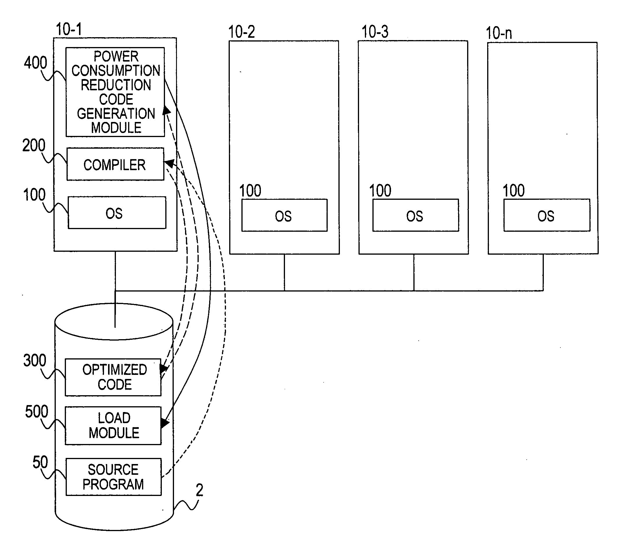
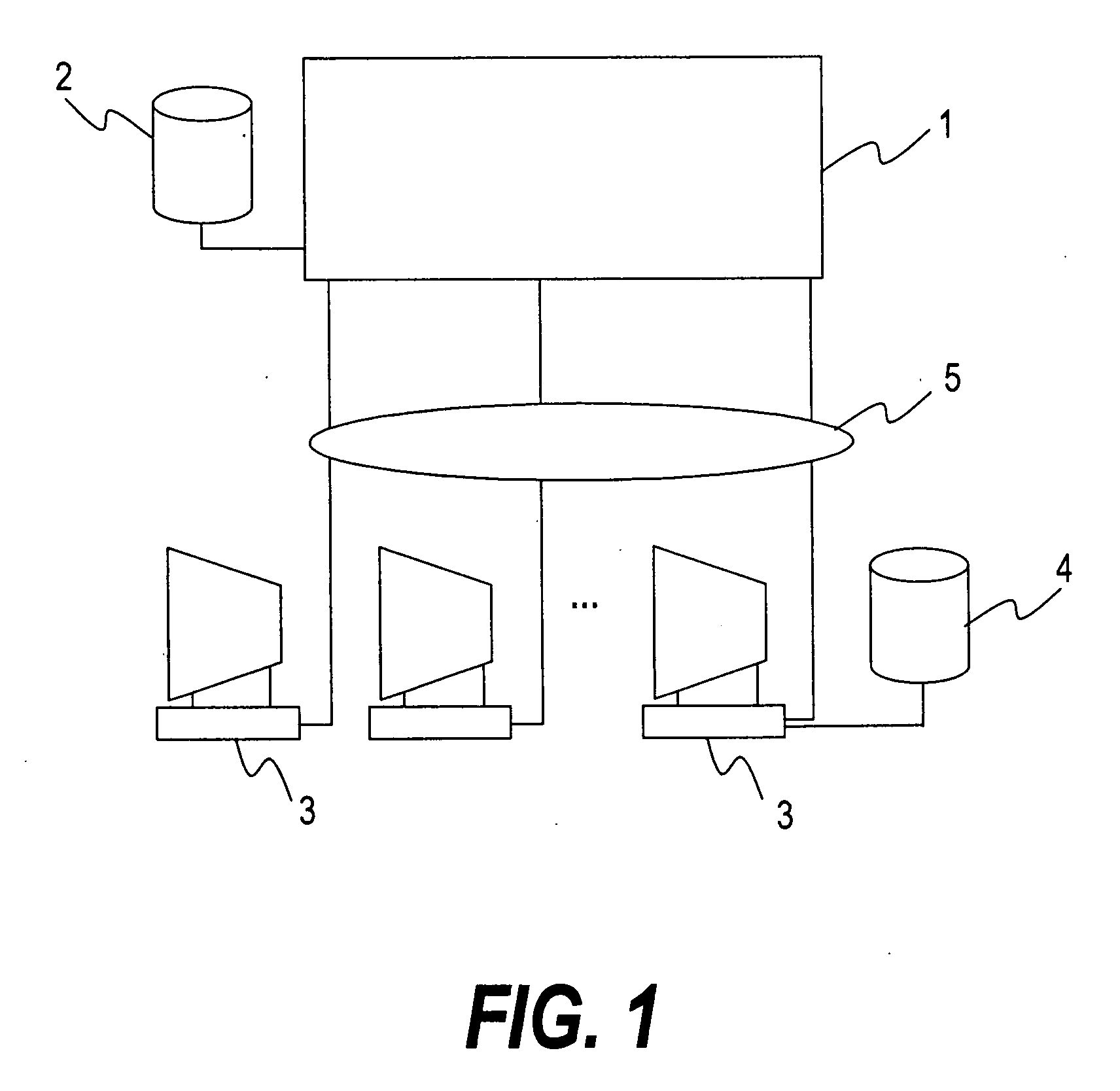
[0034]FIG. 1 is a block diagram showing a computer system according to a first embodiment of this invention. A computer 1 for performing a parallel processing is connected to a storage system 2 which stores a source program, a load module (execution code), a compiler, or data.

[0035]The computer 1 is connected to a plurality of user terminals (clients) 3 through a network 5, so a plurality of users can use the computer 1. Each of the user terminals 3 has a storage system 4 connected thereto, in which data and a source program can be stored. The users of the user terminals 3 each can issue a command for compiling a source program to the computer 1 and execute a load module generated through the compilation to use the result of the operation.

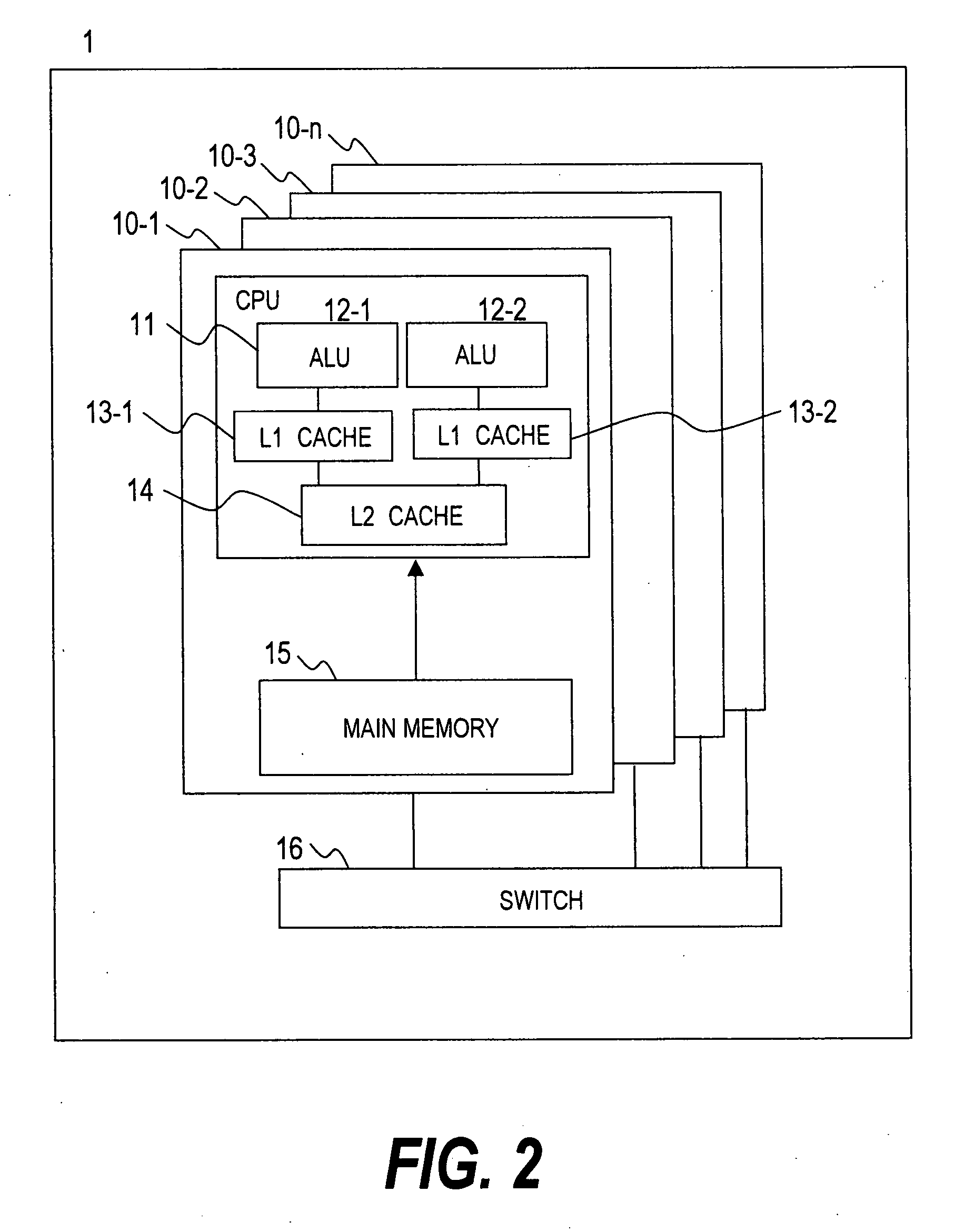
[0036]FIG. 2 is a block diagram showing a configuration of the computer 1. The computer 1 includes a plurality of nodes 10-1 to 10-n and a switch 16 for connecting the nodes 10-1 to 10-n to one another. The switch 16 is connected to a network inter...

second embodiment

[0083]FIGS. 12 and 13 each show a second embodiment, in which the CPU 11 of the first embodiment includes a third level cache memory 17.

[0084]In FIG. 12, the second level cache memory 14 of the CPU 11 includes the third level cache memory 17 on the main memory 15 side. Other configuration of the CPU 11 is similar to that of the first embodiment.

[0085]FIG. 13 shows another subroutine performed by the power consumption reduction code generation module 400 in the step S11.

[0086]In FIG. 13, the steps S20 to S22 and the step S25 are similar to those of the first embodiment of FIG. 10. Processing performed in and after a step S31 for adding a power consumption reduction code is different from that of the first embodiment.

[0087]When it is determined in the step S22 that the CPU load ratio is equal to or lower than the shifting condition, a power consumption reduction code is added in and after the step S31 because memory access time is long in the target area and the CPU 11 is highly likel...

third embodiment

[0095]FIG. 14 shows a third embodiment, in which the power consumption reduction code generation module 400 of the first embodiment is incorporated into a compiler. Other configuration of the third embodiment is similar to that of the first embodiment.

[0096]An optimized code generation module 230 of a compiler 200A outputs an optimized code to the power consumption reduction code generation module 400. The power consumption reduction code generation module 400 analyzes the optimized code and outputs the load module 500 to which a power consumption reduction code has been added as in the first embodiment.

[0097]In this example, it is not necessary to output an intermediate code, which makes it possible to obtain the load module 500 even more quickly.

[0098]It should be noted that in the first to third embodiments, the loop operation is selected as the target area to which the power consumption reduction code is to be added, from the area in which the optimized code which has been read ...


PUM


Abstract

Provided is a method of reliably reducing power consumption of a computer, while promoting prompt compilation of a source code and execution of an output code. The method according to this invention includes the steps of: reading a code which is preset and analyzing an amount of operation of the CPU and an access amount with respect to the cache memory based on the code; obtaining an execution rate of the CPU and an access rate with respect to the cache memory based on the amount of operation and the access amount; determining an area in which the access rate with respect to the cache memory is higher than the execution rate of the CPU, based on the code; adding a code for enabling the power consumption reduction function to the area; and generating an execution code executable on the computer, based on the code.

Description

CLAIM OF PRIORITY[0001]The present application claims priority from Japanese application P2006-213342 filed on Aug. 4, 2006, the content of which is hereby incorporated by reference into this application.BACKGROUND OF THE INVENTION[0002]This invention relates to a technique for efficiently operating a plurality of CPUs, in particular, a compiler which generates a program for performing a parallel processing.[0003]In recent years, along with microfabrication of a semiconductor device due to the advancement of a semiconductor manufacturing technology, it has become possible to integrate an enormous number of transistors. The advancement of the semiconductor manufacturing technology has also raised the clock frequency at which a CPU (processor) operates. However, power consumption of the CPU and power consumption during standby due to leakage currents have also been increased. Therefore, studies have been made to improve a processing capability of a CPU with a minimum consumption of po...

Claims


Application Information

Patent Timeline
Patent Type & Authority Applications(United States)
IPC IPC(8): G06F1/00
CPCG06F1/3203Y02B60/181G06F8/4432Y02D10/00
Inventor TAKAYAMA, KOICHISUKEGAWA, NAONOBU
Owner HITACHI LTD
Why Eureka
Try Eureka