Polymer-coated inorganic membrane for separating aromatic and aliphatic compounds
a polymer-coated inorganic membrane and aromatic and aliphatic compound technology, applied in the direction of membranes, separation processes, filtration separation, etc., can solve the problems of high cost of manufacture, complex steps, and a large amount of waste of resources
- Summary
- Abstract
- Description
- Claims
- Application Information
AI Technical Summary
Benefits of technology
Problems solved by technology
Method used
Image
Examples
example 1
[0027]Diepoxide crosslinked / esterified polyimide-aliphatic polyester copolymers were synthesized from an oligomeric aliphatic polyester diol, an anhydride, a diamine, and a diepoxide or mixtures thereof. To illustrate the synthesis and composition of the new copolymers, a diepoxy n-octane crosslinked / esterified polyimide-polyadipate copolymer (diepoxy n-octane polyethylene imide, [PEI]) membrane was used as an example. In the synthesis, 5 g (0.005 moles) of a 1000 g / mole polyethylene adipate diol (PEA) was reacted with 2.18 g (0.01 moles) of pyromellitic dianhydride (PMDA) to make a prepolymer in the end-capping step (reaction conditions: 165° C. / 6.5 hours). 25 g of dimethylformamide (DMF) was subsequently added. The temperature was decreased to 70° C. The prepolymer was dissolved in a suitable solvent such as dimethylformamide. 1.34 g (0.005 moles) of 4,4′ methylenebis(2-chloroaniline) (MOCA) was subsequently added (dissolved in 5 g DMF). In the DMF solution, one mole of the prepol...
example 2
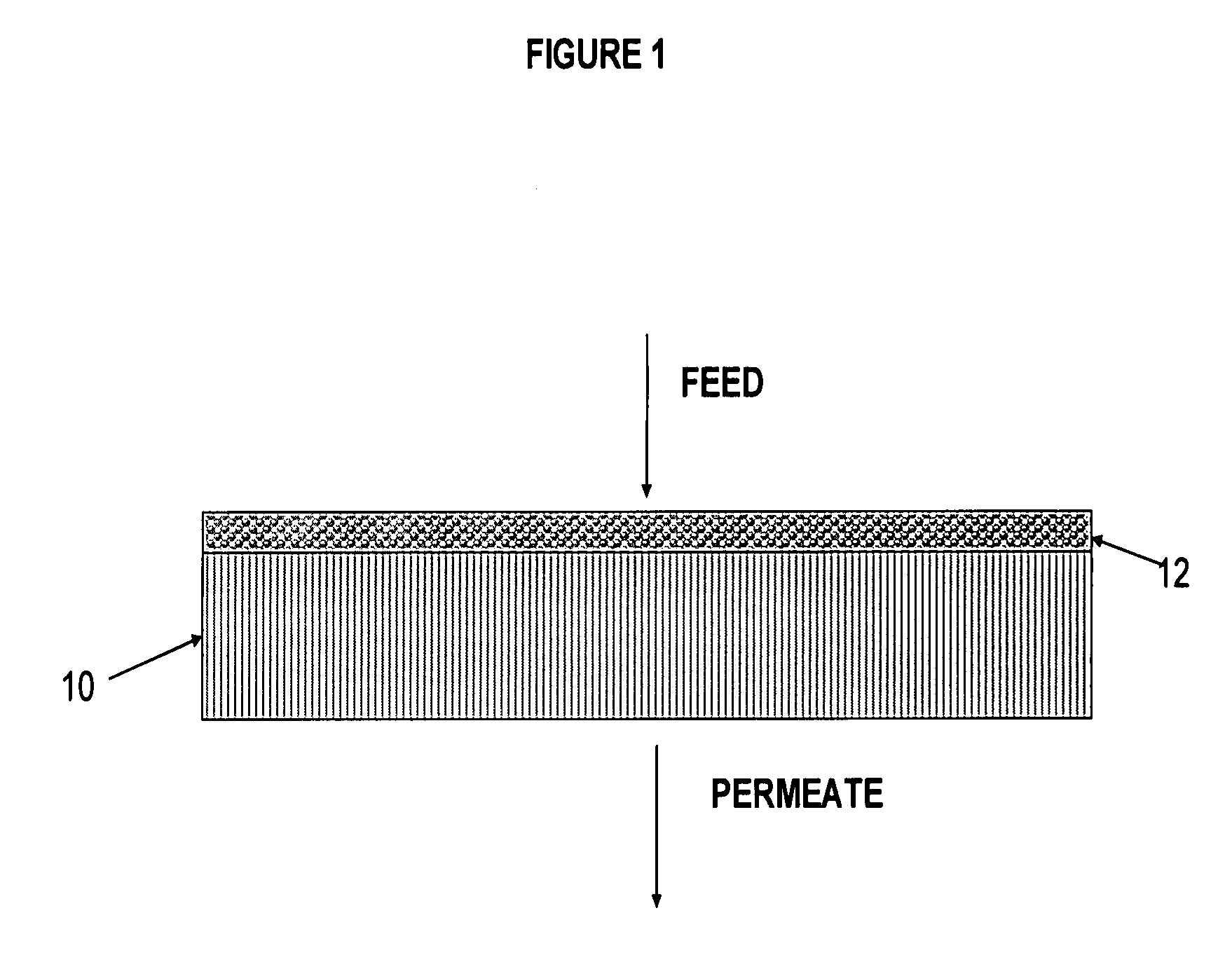
[0030]In this example, the porous, inorganic ceramic monolith support included a silica topcoat. A nominal 0.005 micron pore size silica monolith produced by CeraMem Corp. (Waltham, Mass.)—designated model LM-005-5 (S / N AG 1367) is used in this example. The coating procedure consisted of filling the inside of the monolith via gravity feed with the PEI copolymer solution (C<C*; C=1.0 wt %, where C* is chain overlap concentration) described in Example 1. The dilute solution was subsequently drawn into the interior surface of the monolith with the use of a vacuum positioned on the back side of the monolith. The monolith was placed in a stainless steel container so as to effectively and efficiently pull a vacuum as well as contain the dilute unused copolymer solution. During the coating procedure a vibrating ultrasonic probe was positioned to help ensure coating uniformity and thinness. The diluted solution penetrated and wet substantially the entire monolith structure; however, the ass...
example 3
[0031]A inorganic silica monolith support was coated according to the following procedure.
[0032]A CeraMem, Inc. monolith test module, 1 foot long×1 inch diameter, having 0.005 micron porosity silica coated 2 mm×2 mm channels, was coated with a dilute solution of the PEI polymer precursor, i.e. polyamic acid. 130.7 g of a 2 wt % polymer solution was placed in separatory funnel, gravity fed into the monolith interior channels, and subsequently “pulled” into the membrane monolith structure via a vacuum on the back side of the module. A sonicator probe was then used to dislodge / move any trapped air and / or solvent bubbles in the surface structure of the monolith. The sonicator probe was placed against the metal housing and turned on for approximately 30 seconds. The following sonicator settings were used: output—level 4; %, duty—40%. Laboratory vacuum was then applied on the backside of the ceramic monolith. Vacuum was applied until all of the copolymer solution had been used from the se...
PUM
| Property | Measurement | Unit |
|---|---|---|
| glass transition temperature | aaaaa | aaaaa |
| temperature | aaaaa | aaaaa |
| molar ratio | aaaaa | aaaaa |
Abstract
Description
Claims
Application Information
 - R&D
- Intellectual Property
- Life Sciences
- Materials
- Tech Scout
- Unparalleled Data Quality
- Higher Quality Content
- 60% Fewer Hallucinations
Browse by: Latest US Patents, China's latest patents, Technical Efficacy Thesaurus, Application Domain, Technology Topic, Popular Technical Reports.
© 2025 PatSnap. All rights reserved.Legal|Privacy policy|Modern Slavery Act Transparency Statement|Sitemap|About US| Contact US: help@patsnap.com


