Method for Forming Powder Molding Product and Mold Apparatus for Powder Molding

Inactive Publication Date: 2008-02-14
DIAMET CORP
View PDF16 Cites 0 Cited by
  • Summary
  • Abstract
  • Description
  • Claims
  • Application Information

AI Technical Summary

Benefits of technology

[0021]The present invention includes a mold apparatus for powder molding, having a mold body with a through-hole for forming a side of a powder molding product, a lower punch to be fitted into the through-hole from beneath, an upper punch to be fitted into the through-hole from above, a spray member from which a lubricant solution is faced into the through-hole, a heater provided around a molding portion of the powder molding product, the molding portion being defined by the through-hole and the lower punch which is fitted into the through-hole, a temperature control system keeping a temperat

Problems solved by technology

According to the conventional art disclosed in Japanese Registered Patent Publication No. 3309970 since the lubricant dispersed in water is applied to the mold in a state of solid powders, that is, in such state

Method used


Image

  • Method for Forming Powder Molding Product and Mold Apparatus for Powder Molding
  • Method for Forming Powder Molding Product and Mold Apparatus for Powder Molding
  • Method for Forming Powder Molding Product and Mold Apparatus for Powder Molding

Examples


Example

EXAMPLE 1

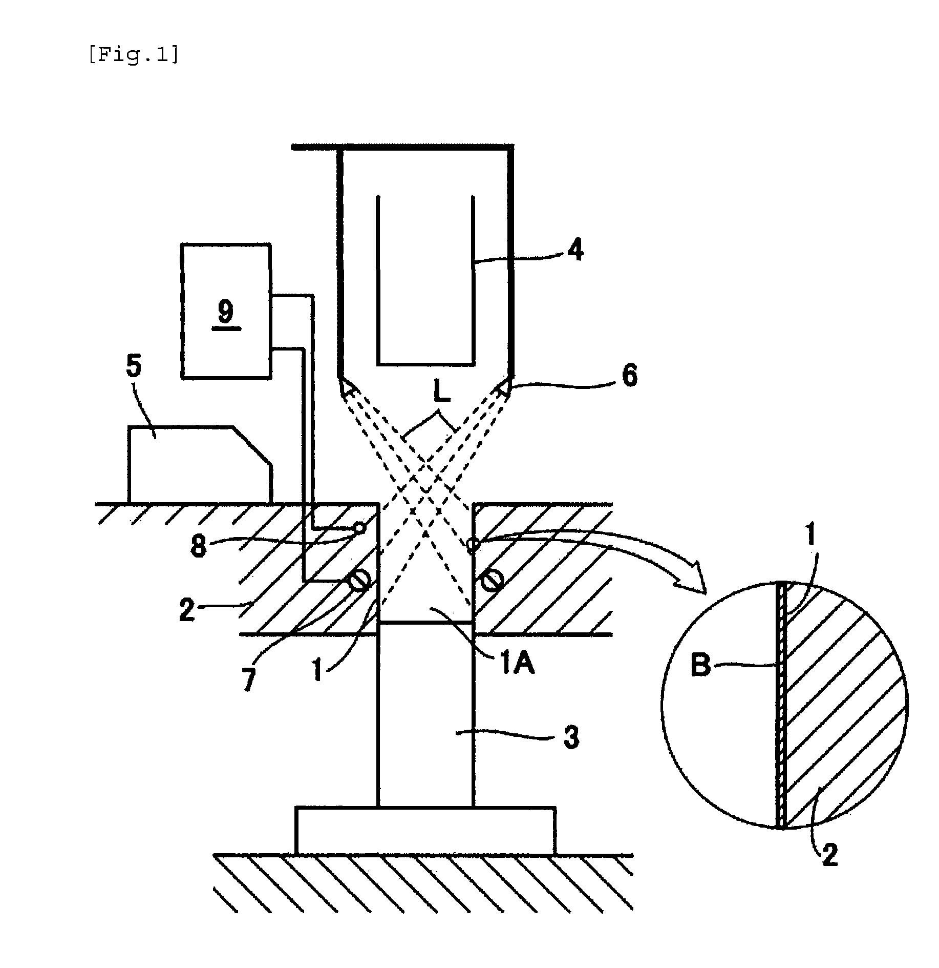
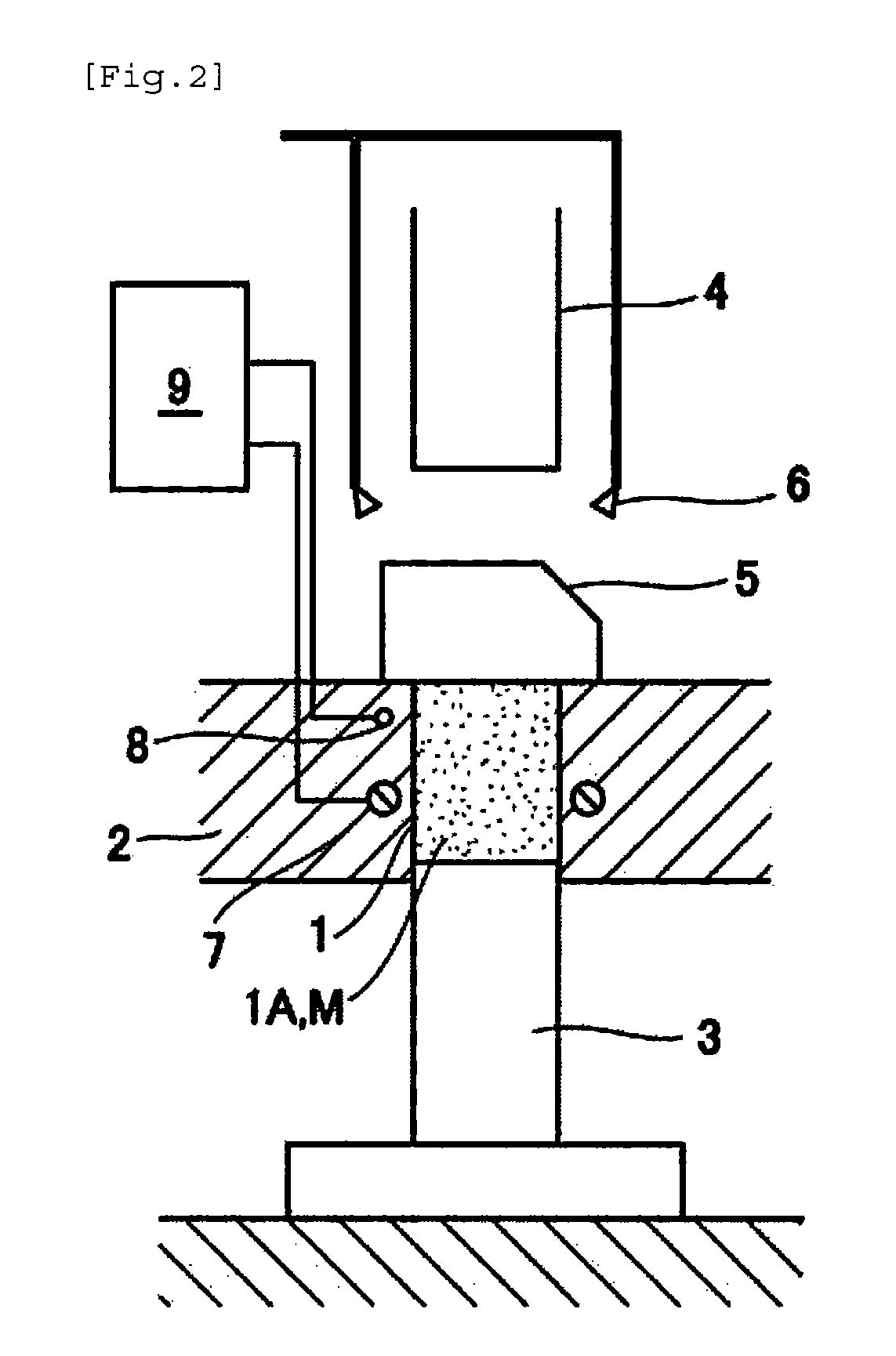
[0036]Example 1 of the present invention will now be explained with reference to FIGS. 1 to 4. FIG. 1 represents a first process. According to the same Figures, numeral 1 designates a through-hole formed in a die 2 serving as a mold for molding sides of a powder molding product A, i.e., compact as a later-described powder molded body. A lower punch 3 is fitted into the through-hole from the underneath thereof and an upper punch 4 is also fitted into the through-hole 1 from the above thereof. A feeder 5, which provides a raw powder M, is slidably provided on an upper surface of the die 2. Above the through-hole 1 is provided a spray member 6 serving as a solution applying means for spraying a lubricant solution L so as to attach the same to a molding portion 1A of the mold. The spray member 6 is arranged so as to face the through-hole 1, and is connected to a tank of the solution L (not shown) via an automatically openable and closable valve (not shown) . A heater 7 and a te...

Example

EXAMPLE 2

[0061]FIG. 5-FIG. 8 represent example 2. in which the same reference symbols as Example 1 will be designated by the same symbols, and their repeated detailed description will be omitted. A surface 10 of the through-hole 1 is formed with a surface treatment layer 11 by hydrophilicity imparting treatment to the surface 10 for improving the wetting action of the aqueous solution L relative to the surface 10, or by arranging hydrophilic material thereon. An angle X of contact of the surface treatment layer 11 relative to the aqueous solution L is smaller than an angle Y of contact of the surface 10, which is made from the material of the die 2 itself, or of the upper surface 2A where the material is exposed, relative to the aqueous solution L (X10 and the upper surface 2A horizontally. And the surface treatment layer 11 is formed by: the thermal spraying, PVD, CVD or shot peening of oxide, fluoride, nitride, chloride, sulfide, bromide, iodide, carbide, hydroxide and etc. having...

Example

EXAMPLE 3

[0066]FIG. 9 and FIG. 10 represent Example 3, in which the same reference symbols as those in Example 1 and Example 2 will be designated by the same symbols, and their repeated detailed description will be omitted. According to the Example 2, the upper surface 2A of the die 2 on which feed 5 is slidably provided is formed with a surface treatment layer 21 by water repellency imparting treatment to the surface 2A for improving its liquid repelling ability (i.e., reducing the wetting action of the aqueous solution L) relative to the surface 2A, or by arranging water repellent material thereon. An angle Y′ of contact of the surface treatment layer 21 relative to the aqueous solution L is larger than an angle X′ of contact of the surface made from the material of the die 2 itself, or in Example 3 the surface 10 of the through-hole 1, relative to the aqueous solution L (Y′>X′), thus enabling the said wetting action to be reduced. The above surface treatment layer 21 may be forme...


PUM

PropertyMeasurementUnit
Temperatureaaaaaaaaaa
Percent by massaaaaaaaaaa
Massaaaaaaaaaa

Abstract

A powder molding product may be formed by a forming portion in a mold body filled with a raw powder. Upper and lower punches are fitted into the forming portion to form the powder molding product. Prior to filling with the raw powder, aqueous solution in which water soluble lubricant having at least 3 g of solubility for 100 g of water is dissolved in water to uniform phase is applied to a mold portion. The aqueous solution is evaporated, thus forming a crystallized layer on the molding portion. The crystallized layer is formed on the peripheral surface of the molding portion for lubrication enabling the reducing of a pressure required for ejecting the powder molding product from the molding portion as well as the improving of the density of the powder molding product.

Description

CROSS REFERENCE TO PRIOR APPLICATION[0001]This is a U.S. national phase application under 35 U.S.C. §371 of International Patent Application No. PCT / JP2005 / 002994 filed Feb. 24, 2005 and claims the benefit of Japanese Application No. 2004-055363, filed Feb. 27, 2004. The International Application was published in Japanese on Sep. 9, 2005 as International Publication No. WO 2005 / 082562 A1 under PCT Article 21(2).FIELD OF THE INVENTION[0002]The present invention relates to a method for forming a powder molding product by filling raw powders in a mold for powder molding, and also relates to a mold apparatus for such powder molding.BACKGROUND ART[0003]A compact powder, which is used for the production of sintered products, is formed by pressing raw powders such as Fe-based powders, Cu-based powders or the like in a mold, and then a sintered body is formed through a sintering process. And in the molding process, the molding product undergoes a press-molding process, using a mold. At the ...

Claims


Application Information

Patent Timeline
IPC IPC(8): B22F3/035B22F3/02B30B11/00B30B11/02B30B15/00
CPCB30B15/0011B22F3/02B22F3/03
Inventor NAKAI, TAKASHIKAWASE, KINYA
Owner DIAMET CORP
Why Eureka
Try Eureka