Method of solid fuel combustion intensification

a solid fuel combustion and intensification technology, applied in the field of power engineering and metallurgy, can solve the problems of unproductive oxidizer loss, precious oxidizer, and the necessity of obtaining oxidizers using additional complex and metal consuming technologies, and achieve the effects of increasing the rate of oxidation, reducing energy expenditure, and increasing the degree of carbon burning

Inactive Publication Date: 2008-02-21
LIMITED LIABILITY RES AND PRODION COMPANY UKRTRANSKOM +1
View PDF4 Cites 14 Cited by
  • Summary
  • Abstract
  • Description
  • Claims
  • Application Information

AI Technical Summary

Benefits of technology

[0014]The comparative analysis with the prototype allows making a conclusion that the claimed solution differs from the prototype by the creation of the low-temperature plasma and electrocatalytic processes in the combustion zone. This leads to the approach of speeds of thermodestruction and electrocatalytic destruction of carbon and hydrocarbons which are desorbed from the coal; to the increase of the rates of oxidation of the carbon-bearing compounds to the carbon dioxide and water, owing to a high concentration of oxygen-containing radicals, to the increase of the carbon burning degree from the solid fuel and economy of the solid fuel. As the catalytic plasma and oxidation processes are brought in one zone, compared to the prototype the energy expenditures are decreased by three orders, which allows achieving a high specific economy of fuel. The fuel expenditures for creation of low-temperature plasma do not exceed 2 to 5% of the energy effect obtained according to the proposed method.

Problems solved by technology

The disadvantages consist in the use of a precious oxidizer, unproductive oxidizer losses due to a large oxygen breakthrough, necessity of obtaining the oxidizer using additional complex and metal consuming technology.
The disadvantages are that the technology was studied at low concentrations of the reacting components which leads to increase of expenditure of energy for generation of the electric discharge.
The disadvantages are high specific power inputs decreasing power efficiency of the process, necessity of fuel mixing and electrostatic atomization, complexity of combustion process regulation.

Method used


Image

  • Method of solid fuel combustion intensification
  • Method of solid fuel combustion intensification
  • Method of solid fuel combustion intensification

Examples


Embodiment Construction

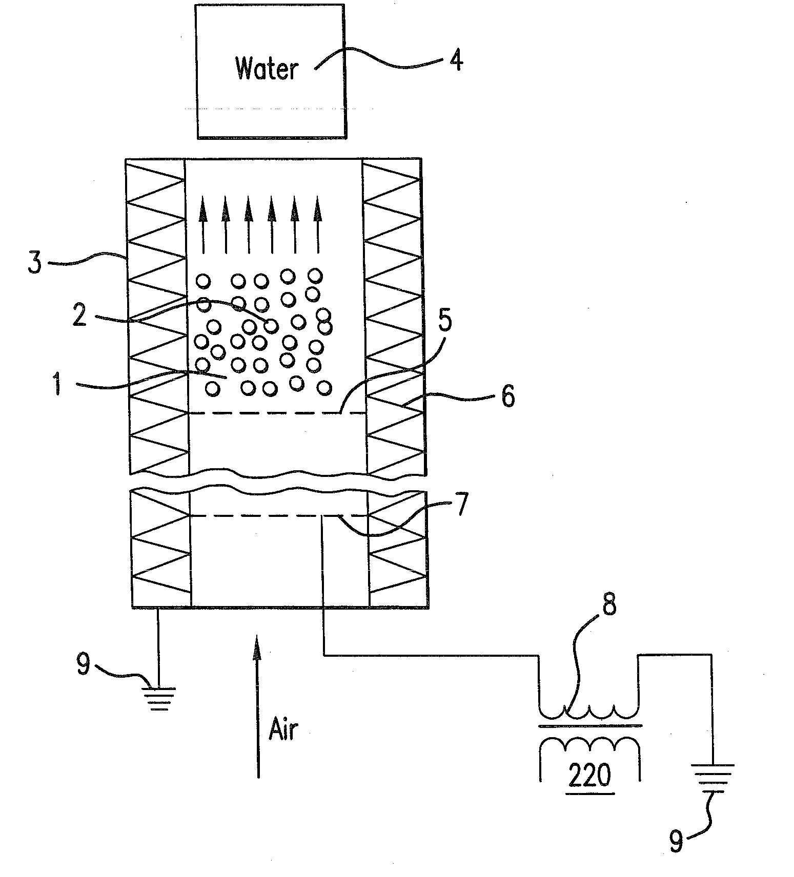
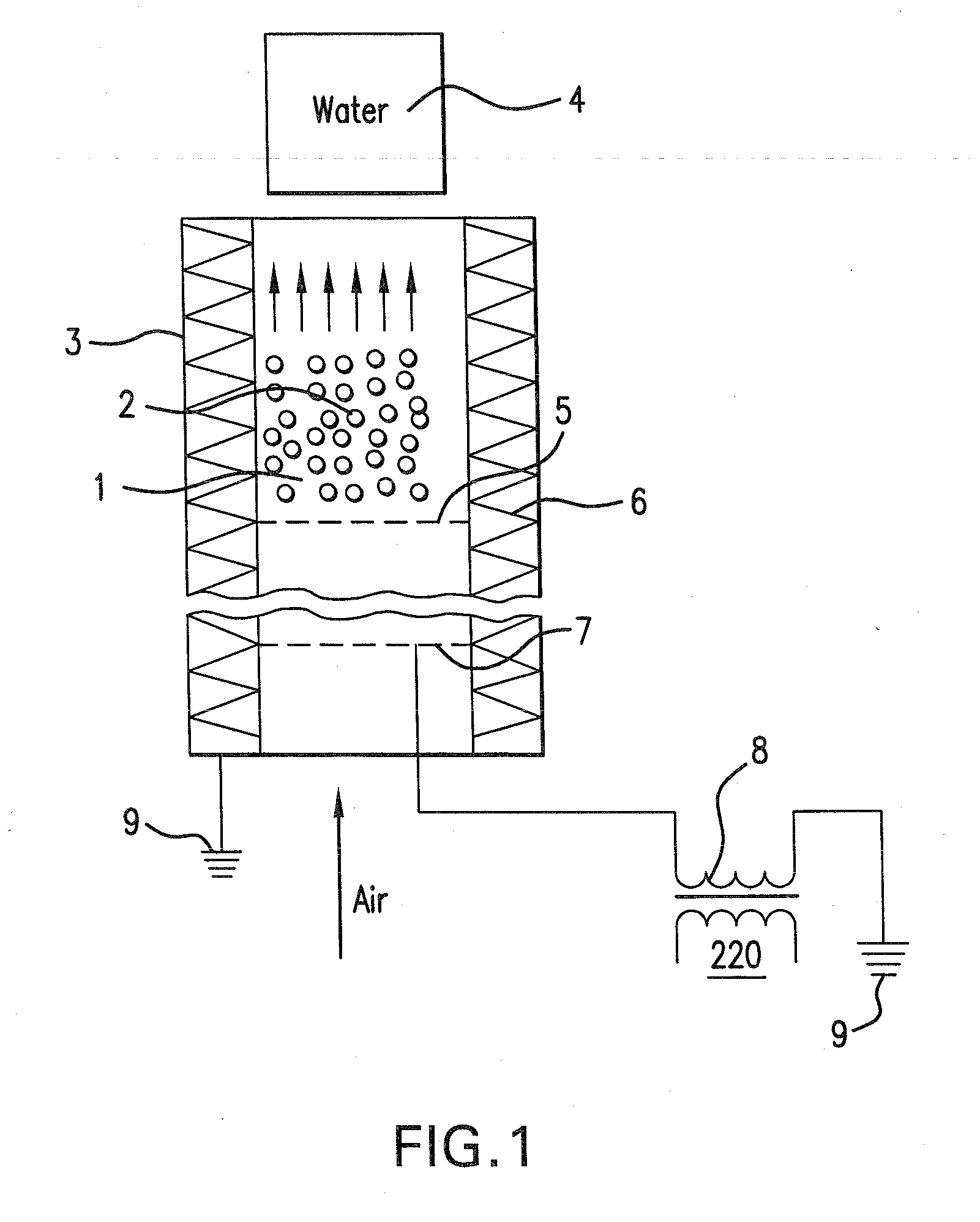
[0021]The air flow containing pulverized solid fuel comes into the combustion chamber 1. It passes through the grid 7, bottom grate 5, and arrives into the zone 2. Electric ignition 3 provides the ignition temperature of the fuel-air mixture and after that it is switched off. The stationary combustion process is established which is defined by the heating rate of the precisely measured volume of the heat-transfer medium 4 (water in our case). The 5 to 20 kV voltage is supplied from the power supply 8, 9 to the grid 7 coated with the catalyst enhancing the combustion process. This mode is defined by the heating rate of the equal volume of the heat-transfer medium.

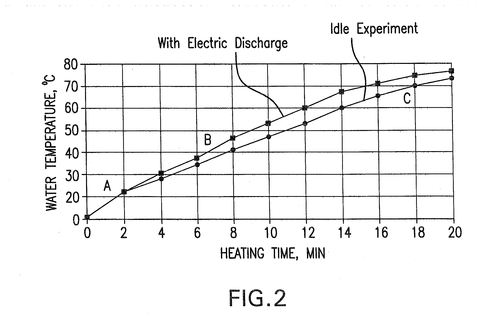
[0022]FIG. 2 shows dependence of the water temperature variation from the time when carrying out idle experiment and with the discharge. When coal is combusted with the discharge water heating is accelerated which is evidence of the release of a larger amount of heat as compared to the idle experiment. (On the curves shown t...


PUM


Abstract

The substance of the invention consists in the combustion of the fuel-air mixture in the electric field by means of the catalyst located in the combustion zone and to which high voltage is applied, which results in reduction of activation energies of all endothermic combustion phases due to the formation of oxygen atoms, carbon radicals and oxygen-containing radicals.
Technical result: introduction of the catalyst in the combustion zone minimizes energy expenditure for creation of the low-temperature plasma, allows to increase the temperature in the combustion zone, to reduce activation energy of all endothermic processes taking place at the initial phase of combustion and to reduce carbon content in the ash and to achieve considerable fuel economy.

Description

BACKGROUND OF THE INVENTION[0001]The method relates to the power engineering, metallurgy, and namely, to the solid fuel combustion: coal, peat, wood.[0002]The process of solid fuel combustion is well known. So far, a considerable number of methods of solid fuel intensification are known. One of the methods consists in combustion intensification by increasing oxygen concentration in the flame, resulting in increasing of atoms and oxygen-containing radicals in the combustion zone.[0003]The method of oxygen-convector steel melting is known (see Kazakov N. F., Osokin A. M., Sishkova A. P. Technology of metals and other structural materials, 1975-688 p.). The substance of this method consists in the iron oxygen blow through the lance. During the high-temperature mass oxygen blowing oxidation of hardly oxidized additives is achieved. The highest oxidation of additives takes place at the oxygen jet-metal interface.[0004]The disadvantages consist in the use of a precious oxidizer, unproduct...

Claims


Application Information

Patent Timeline
Patent Type & Authority Applications(United States)
IPC IPC(8): F23Q11/00F23B90/00
CPCF23B7/00F23C99/001F23C13/00F23B90/00
Inventor STOLYARENKO, HENNADIY STEPANOVYCHVIAZOVIK, VITALII MYKOLAYOVYCHVODIANYK, OLEH VOLODYMYROVYCHMARTSINYSHYN, YURIY DANYLOVYCHBADKO, GENNADII JURIEVYCH
Owner LIMITED LIABILITY RES AND PRODION COMPANY UKRTRANSKOM
Why Eureka
Try Eureka