Low loss photonic waveguide having high index contrast glass layers

a high-index contrast, glass layer technology, applied in the direction of optical waveguide light guide, instruments, etc., can solve the problems of limiting the amount of optical power that can be transmitted through the fiber, preventing them from realizing their full theoretical potential, and causing distortion of the shape of the optical signal, etc., to achieve the effect of increasing the bandwidth capacity of the resulting fiber, and reducing the cost of production

Inactive Publication Date: 2008-02-28
CORNING INC
View PDF13 Cites 19 Cited by
  • Summary
  • Abstract
  • Description
  • Claims
  • Application Information

AI Technical Summary

Benefits of technology

[0012]Because the Bragg fiber in the invention may be formed entirely of glass compositions, it may be easily manufactured by conventional optical fiber fabricating techniques on a large scale, and with relatively few steps. The resulting fiber is mechan

Problems solved by technology

In addition to signal attenuation, cores formed from doped silica also induce distortions in the shape of the optical signal as a result of optical non-linearities.
Finally, the solid core of doped silica limits the amount of optical power that can be transmitted through the fiber due to damage of glass from high optical power, the damage being caused by the intrinsic absorption of the bulk glass through the formation of absorbing color centers, or from absorption due to contamination of the end facets.
Unfortunately, there are a number of shortcomings associated with known Bragg optical fibers whic

Method used


Image

  • Low loss photonic waveguide having high index contrast glass layers
  • Low loss photonic waveguide having high index contrast glass layers
  • Low loss photonic waveguide having high index contrast glass layers

Examples


Embodiment Construction

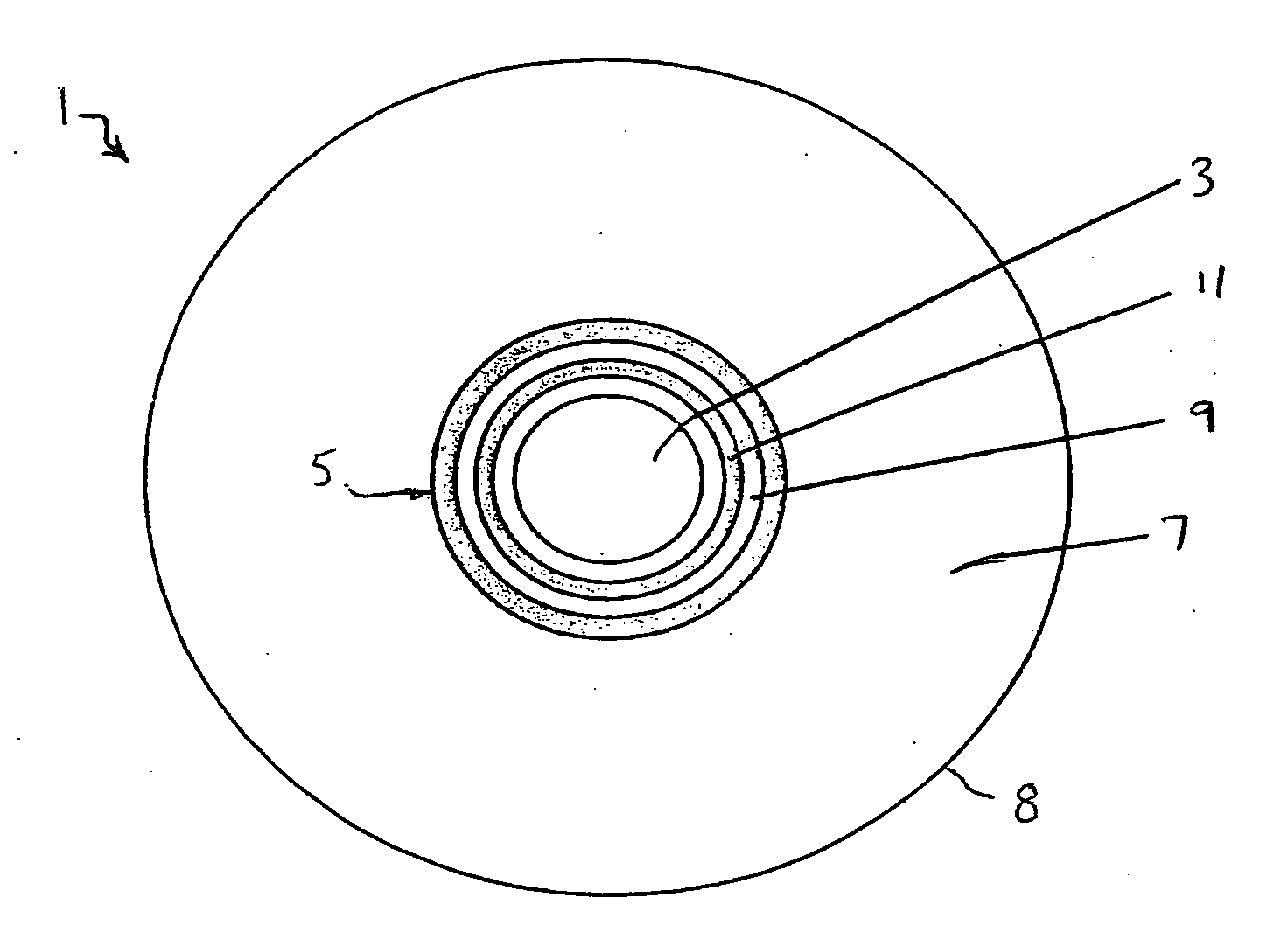
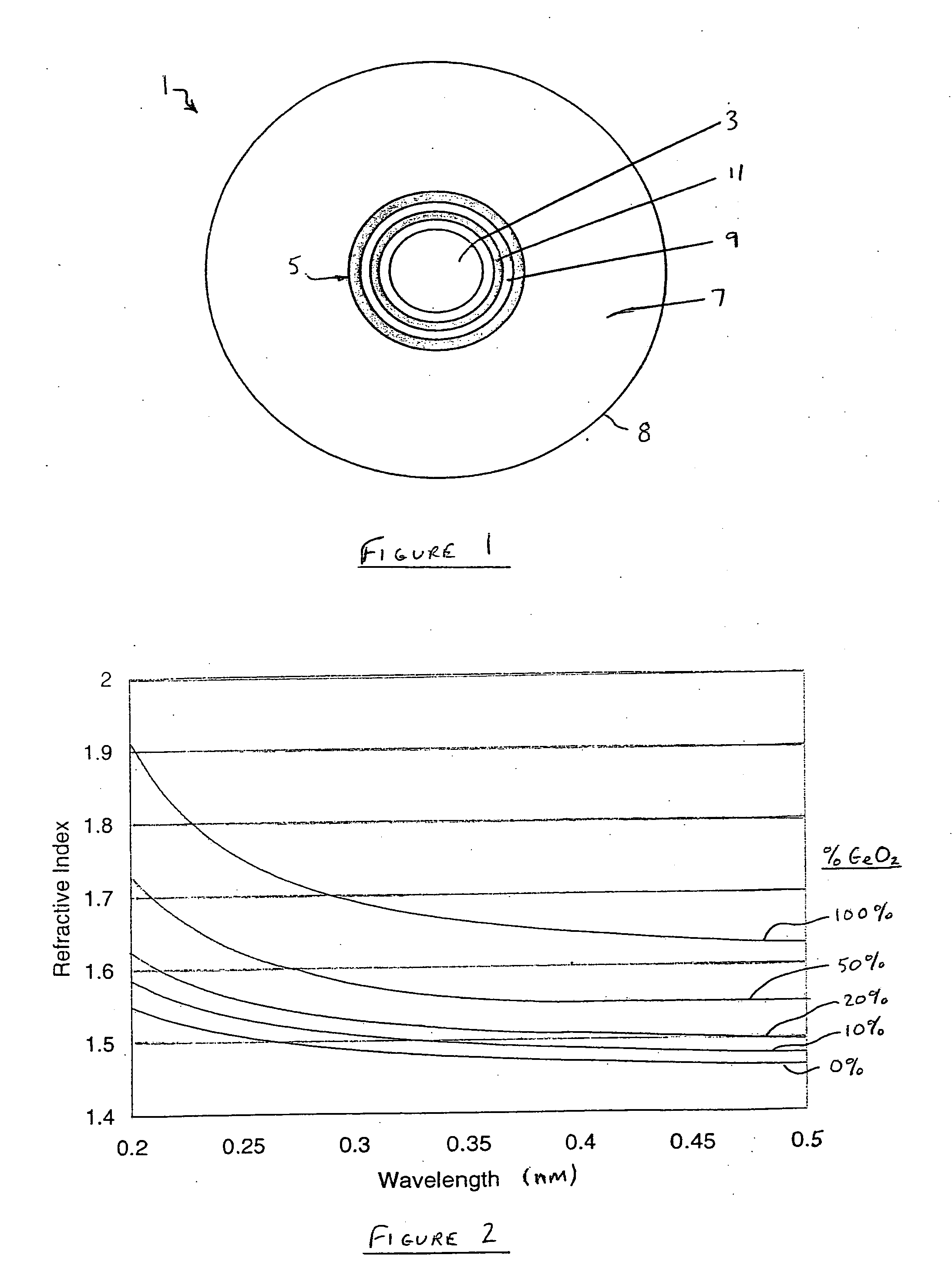
[0021]With reference now to FIG. 1, the photonic Bragg optical fiber waveguide 1 that forms the photonic crystal waveguide of the invention generally comprises a dielectric core region 3 that extends along the central access of the fiber 1, and a dielectric confinement region 5 that surrounds the core region 3. The dielectric core region may be between about 100 nm and 500 microns (for example, 250 nm, 500 nm, or 100 μm) in diameter, while the dielectric confinement region may be between about 500 nm and 100 microns in thickness (for example, 250 nm, 500 nm, 10 μm, or 50 μm). An outer silica cladding 7 in turn surrounds the dielectric confinement region 5 and defines the outer surface 8 of the fiber 1 as shown. The cladding may be between 10 microns to 1000 microns in thickness, and more preferably 50 to 200 microns thick.

[0022]The dielectric core region 3 is preferably air for its very low optical attenuation properties, and for its relative ease of manufacture. However, the dielec...


PUM


Abstract

A low-loss photonic waveguide in the form of a Bragg optical fiber is provided that includes a dielectric core region extending along a waveguide axis that is characterized by a low amount of Rayleigh scattering, and a dielectric confinement region surrounding the dielectric core region that includes alternating layers of different glass compositions having relative refractive index differences that are at least 0.10, and preferably at least 0.30. The core region may be formed from air. The confinement region includes alternating high and low index glass layers wherein the high index layers are substantially pure silica mixed with index raising dopants that form enough % of the high index glass layers by weight to achieve the aforementioned 0.10 difference in indices of refraction, while the low index glass layers may be either substantially pure silica, or silica mixed with index lowering dopants to increase the index contrast between the layers. The use of alternating high and low index glass layers to form the dielectric confinement region allows the Bragg fiber to be usually manufactured on a large scale via conventional fiber optic fabricating techniques with relatively few steps. The resulting fiber is capable of conducting high photonic power levels, and is particularly compatible with short photonic wavelengths, such as ultraviolet light.

Description

BACKGROUND OF THE INVENTION[0001]1. Field of the Invention[0002]This invention generally relates to photonic crystal waveguides, and is specifically concerned with a Bragg optical fiber waveguides having a dielectric confinement region formed from alternating layers of glass having high-contrast optical indices.[0003]2. Description of the Related Art[0004]Optical waveguides in the form of optical fibers are well known in the prior art, and are used to transmit optical signal information between remote locations. The most common type of optical fiber includes a doped silica core region extending along its central axis surrounded by an undoped silica cladding that has a refractive index less than that of the core region. Optical signals are confined along the core region via total internal reflection (TIR) that results from the contrast in indices of refraction along the core-cladding interface. Almost all such index-guided optical fibers are silica-based in which one or both of the c...

Claims


Application Information

Patent Timeline
IPC IPC(8): G02B6/032
CPCG02B6/032G02B6/02304
Inventor LI, MING-JUNNOLAN, DANIEL ALOYSIUSTRUESDALE, CARLTON MAURICEWEST, JAMES ANDREW
Owner CORNING INC
Why Eureka
Try Eureka