Apparatus and method for delivery of biologic sealant

a technology of biologic sealant and applicator, which is applied in the direction of instruments, prosthesis, peptide/protein ingredients, etc., can solve the problems of prone to clogging of the prior delivery device shown in u.s. pat. no. 6,468,527, and achieve the effects of facilitating mixing of components, improving set-up time, and prolonging pain reli

Active Publication Date: 2008-03-13
PAUZA KEVIN
View PDF19 Cites 50 Cited by
  • Summary
  • Abstract
  • Description
  • Claims
  • Application Information

AI Technical Summary

Benefits of technology

[0016] Advantageously, the device, methods, and kit of this invention facilitate extended pain relief for patients with discogenic pain, wherein for example nucleus pulposus leaks out of the disc through defects (e.g. tears or fissures) in the annulus fibrosus. Surprisingly, it has been found that the device of this invention which employs an outer introducer needle and an inner needle within the introducer needle, wherein the tip of the inner needle does not protrude past the distal tip of the outer introducer needle, and in one embodiment is approximately one inch from the distal tip of the outer introducer needle, provides a final fibrin sealant clot with surprising properties. This needle configuration facilitates mixing of the components of the fibrin sealant (or other biologic sealant) to provide improved set-up time (or “work time”), less viscosity with slower set up to afford easier use in practice and higher penetration of sealant into tears, fissures, and so forth, enhanced mechanical properties of the final sealant including greater elasticity (easier to deform) with slightly less failure load (i.e., the force required to make a permanent rupture), approximately a 200% improvement in fracture toughness (i.e., need twice as much energy to break the sealant as compared

Problems solved by technology

However, the inventors herein have recognized that the prior delivery device shown in U.S.

Method used


Image

  • Apparatus and method for delivery of biologic sealant
  • Apparatus and method for delivery of biologic sealant
  • Apparatus and method for delivery of biologic sealant

Examples


example 1

Fluoroscopic Transforaminal Epidural Injection

[0057] With a patient in the prone position on the imaging table, a fluoroscope is positioned and adjusted to locate the intervertebral foramen of the affected nerve root. A curved 22 ga.×3.5″ needle is introduced after anesthetizing the skin and deep tissue. The needle is advanced under direct fluoroscopic vision to a position in the anterior epidural space. Positioning of the needle is verified by a lateral fluoroscopic view and by injecting contrast medium through the needle. Such positioning may or may not require further adjustment. If adjusted, location of the needle is once again verified. Advancement of the needle into the correct region may stimulate pain in a manner consistent with the initial complaint. Therefore, needle placement may also be verified by the patient's pain recognition. The epidural space is anesthetized with injectable anesthetic. The fibrin sealant of fibrinogen and thrombin (prior to clotting) is then intro...

example 2

Fluoroscopic Guided Intra-Discal Injection

[0060] After sterile preparation, an introducer needle is advanced in oblique projection to a superior articular process. A curved spinal needle is advanced through the introducer needle into the disc. Both anterior-posterior and lateral fluoroscopic projections are used to confirm proper needle placement. If the needle placement needs to be adjusted, placement is again confirmed fluoroscopically. A contrast agent is injected to confirm needle placement. In patients with chemical radiculitis, the contrast agent can be observed to be leaking through the annular fissures and / or intra-discal pathology can be identified. Once the needle is properly positioned in the intra-discal space, the fibrin sealant is injected using the delivery device of this invention such as shown in the FIGS. The fibrin sealant is observed to force the contrast agent from the intra-discal space as it seals the annual fissures. Alternatively, the contrast agent is inje...

example 3

Comparative Assessment of the Physical Property of Clots

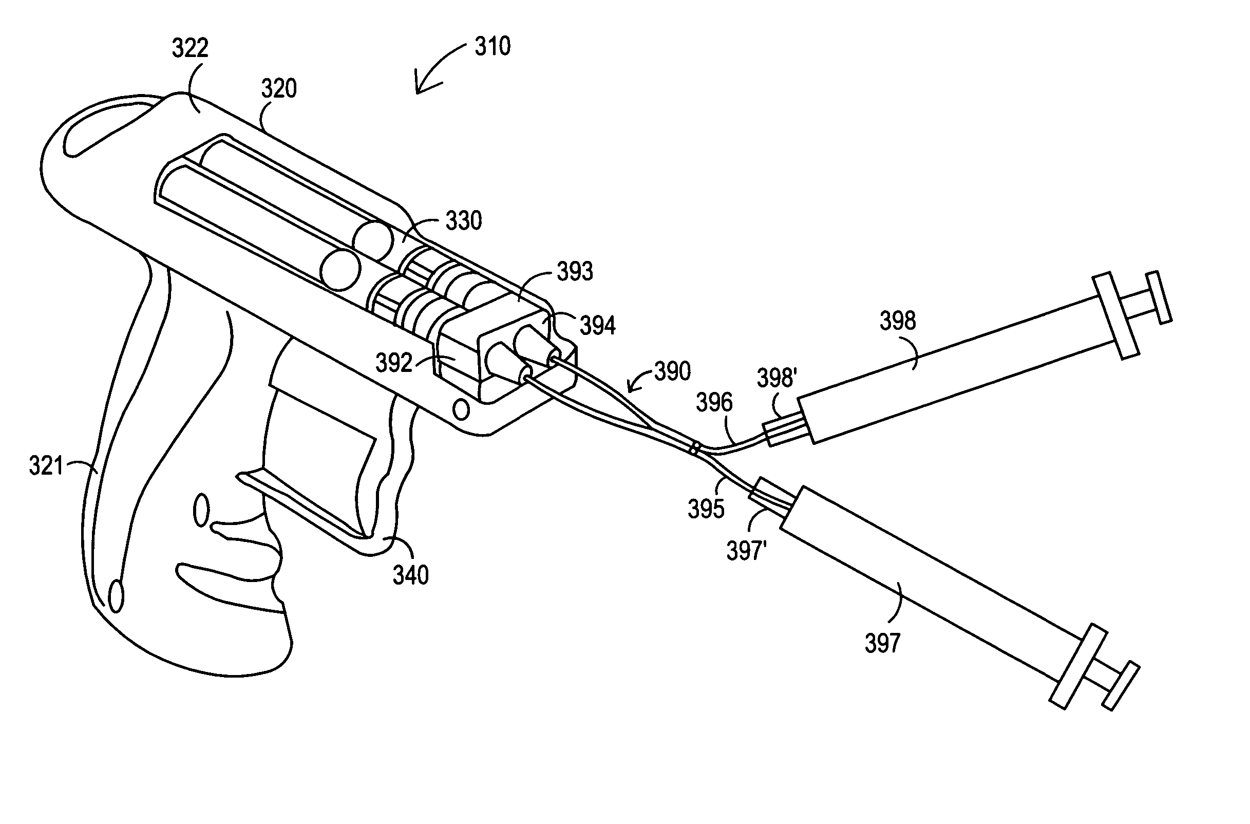
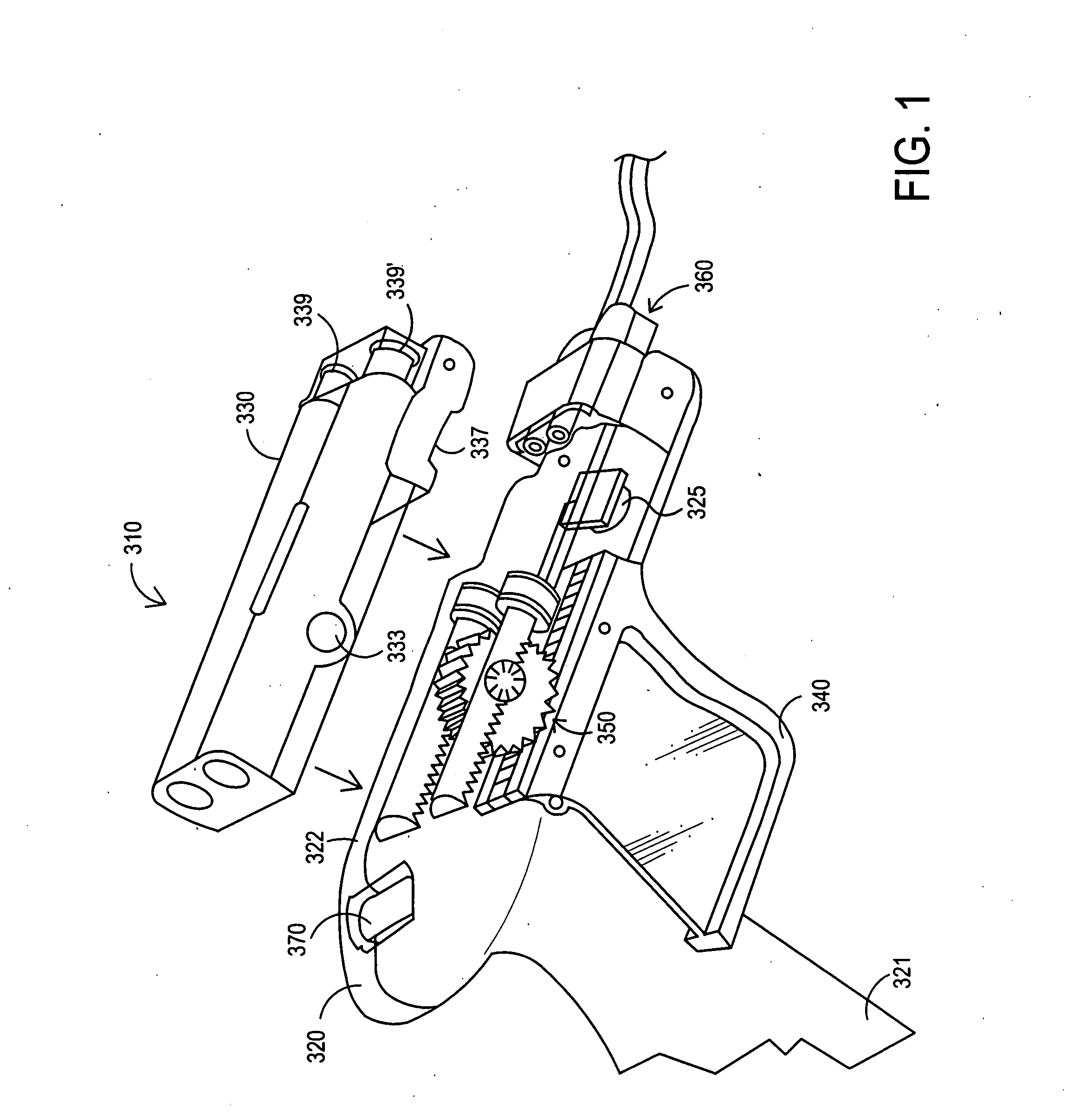
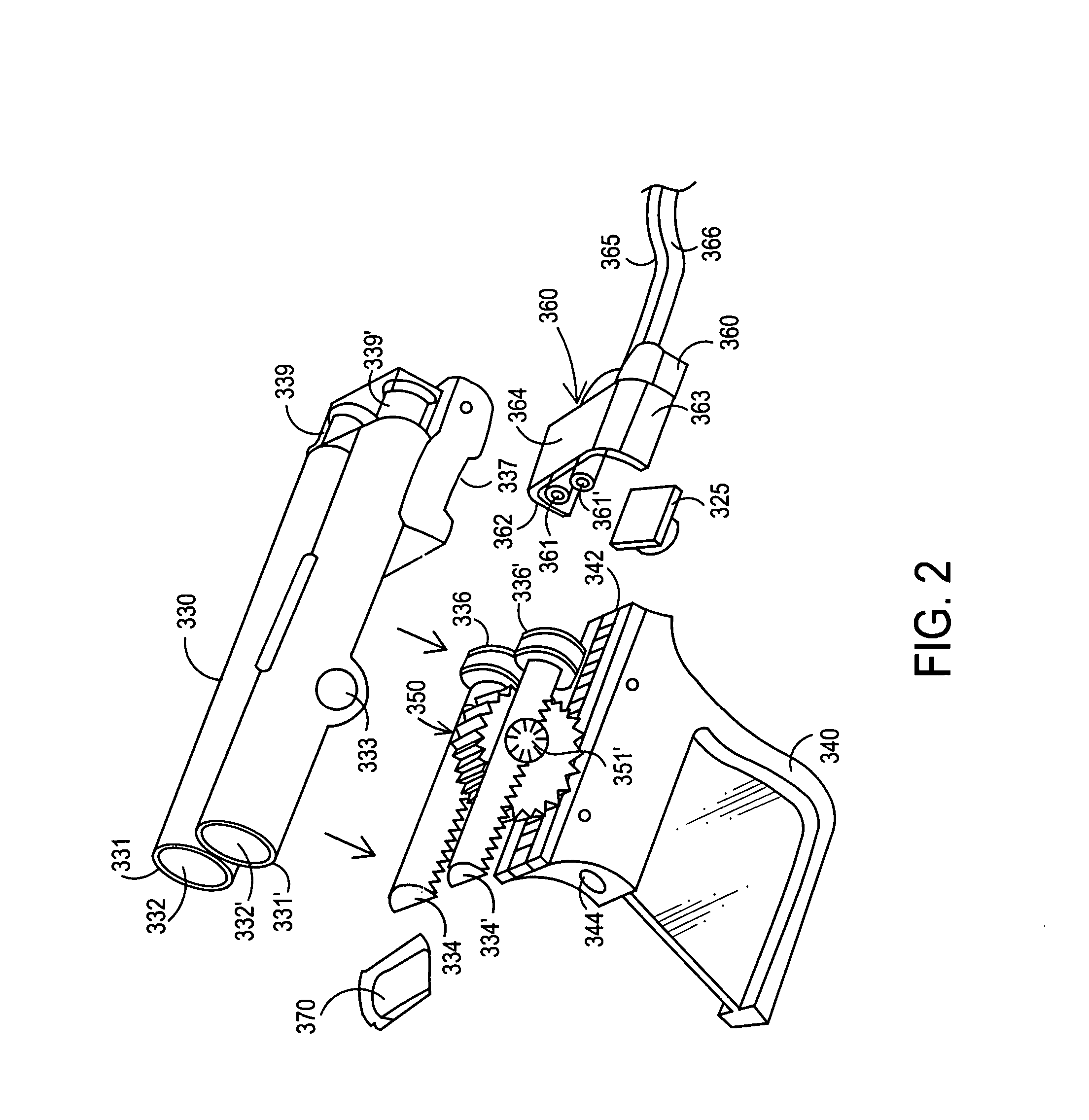
[0061] TISSEEL VH S / D fibrin sealant was prepared according to manufacturer guidelines. The reactive components were mixed and delivered using a DUPLOJECT delivery device or the deliver device of this invention as shown in FIGS. 1-8 and 9-12.

[0062] In the device of this invention used in this example, the tip of the inner needle was approximately one inch short of the distal tip of the introducer needle. The inner needle was a 22 gauge needle and the outer needle was an 18 gauge needle. As used herein including Table 1, “Biostat” refers to the device used in the tests constructed according to this invention.

[0063] A DUPLOJECT delivery device is the standard device used currently for mixing and providing fibrin sealant. The DUPLOJECT device includes dual syringes that feed fibrinogen solution and thrombin solution into a Y-connector where mixing of the solutions is initiated. The DUPLOJECT device is equipped with a standard o...


PUM

PropertyMeasurementUnit
Pressureaaaaaaaaaa
Diameteraaaaaaaaaa

Abstract

A device for delivery of biologic materials, comprising: a cartridge having at least two cylinder bores for fluids to be delivered, wherein each cylinder includes an exit port for a fluid, a plunger within each cylinder for pushing the fluids out of the cylinder, a housing adapted to receive the cartridge, wherein the housing or cartridge includes an adaptor to receive and lock a manifold that operably connects to the exit ports of the cartridge, at least two toothed rams, wherein each toothed ram is at least partially within a cylinder bore, a trigger connected to the housing, wherein the trigger includes a toothed drive rack, a toothed wheel assembly that cooperates with the toothed drive rack and with the toothed rams, as well as methods of making the device, methods of using the device to treat discs, kits including the device.

Description

[0001] This application claims priority to U.S. provisional application No. 60 / 854,413, filed Oct. 24, 2006, to U.S. provisional application No. 60 / 623,600, filed Oct. 29, 2004 and is a continuation-in-part of U.S. application Ser. No. 11 / 205,760, filed Aug. 17, 2005, of U.S. application Ser. No. 11 / 205,784, filed Aug. 17, 2005, and of U.S. application Ser. No. 11 / 205,775, filed Aug. 17, 2005, and this application claims priority to U.S. provisional application No. 60 / 764,019, filed Feb. 1, 2006, and this application claims priority to U.S. provisional application No. 60 / 764,020, filed Feb. 1, 2006, all of which are incorporated herein by reference.FIELD OF THE INVENTION [0002] The disclosure herein generally relates to an apparatus and method for the delivery of a biologic sealant such as fibrin sealant. BACKGROUND OF THE INVENTION [0003] Fibrin sealants, and glues, are well known and are used extensively in various clinical settings. Such sealants are indicated as adjuncts to hemo...

Claims


Application Information

Patent Timeline
IPC IPC(8): A61M5/00A61M37/00B65D69/00
CPCA61B17/00491Y10T29/49826A61B2017/00495A61K38/363A61K38/482A61K45/06A61L24/106A61L27/225A61L27/50A61L27/54A61L2300/00A61L2400/06A61L2430/38B05C17/00553B05C17/0116A61B17/0057A61K2300/00
Inventor WHEELER, JOHNWHIPPLE, GARYBOCCUTI, A.WASHBURN, THOMASGENTILE, ANDREWRATZ, J.SPIRIDIGLIOZZI, JOHN
Owner PAUZA KEVIN
Why Eureka
Try Eureka