Tunnel magnetoresistive element and manufacturing method thereof

a technology of which is applied in the field of tunnel magnetoresistive elements and manufacturing methods thereof, can solve the problems of poor film surface smoothness after formation, inability to obtain stable anti-ferromagnetic exchange coupling between the first and second pinned magnetic layers, and inability to obtain excellent crystal structure of mgo, etc., to prevent deterioration of film characteristics, improve performance, and excellent anti-ferromagnetic exchange coupling

Inactive Publication Date: 2008-03-13
FUJITSU LTD
View PDF4 Cites 4 Cited by
  • Summary
  • Abstract
  • Description
  • Claims
  • Application Information

AI Technical Summary

Benefits of technology

[0014]In keeping with one aspect of this invention, a magnetoresistive element is formed by sequentially laminating an underlayer, an anti-ferromagnetic layer, a first pinned magnetic layer, a non-magnetic intermediate layer, a second pinned magnetic layer, a tunnel barrier layer, a free magnetic layer and a protection layer. The first pinned magnetic layer is smoothed before the non-magnetic intermediate layer is laminated. Since the first pinned magnetic layer is smoothed, the non-magnetic intermediate layer laminated thereafter is also smooth, and stable antiferromagnetic exchange coupling between the first pinned magnetic layer and the second pinned magnetic layer can be obtained. Moreover, the tunnel barrier layer laminated thereon is also smoothed, so that thickness can be reduced without generation of one or more pinholes.
[0015]Smoothing is conducted so that the average roughness Ra of the center line is 0.3 nm or less. When the average roughness Ra of the center line is 0.3 nm or less, the smooth surface is comparable to that when the Pt—Mn alloy, for example, is used as the anti-ferromagnetic layer and therefore excellent magnetoresistive characteristics can be obtained.
[0016]Moreover, the anti-ferromagnetic layer is preferably formed of an Ir—Mn alloy. When the Ir—Mn alloy is used as the anti-ferromagnetic layer, smoothness of the film surface after formation thereof is poor in comparison with that when the Pt—Mn alloy, for example, is used. Moreover, stable anti-ferromagnetic exchange coupling between the first and second pinned magnetic layers cannot be obtained even when the non-magnetic intermediate layer is laminated on the film. However, stable anti-ferromagnetic exchange coupling between the first and second pinned magnetic layers can be attained by smoothing the first pinned magnetic layer. In addition, when the Ir—Mn alloy is used as the anti-ferromagnetic layer, smoothing of the tunnel barrier layer can provide a significant improvement in performance.
[0020]The smoothing process of the first pinned magnetic layer can be conducted with a gas cluster ion beam or inverse sputtering process. As the smoothing means, the gas cluster ion beam or inverse sputtering process, which can be conducted in the identical vacuum condition, is employed to prevent deterioration of film characteristics.
[0021]An Ir—Mn alloy can be used as the anti-ferromagnetic layer, while the MgO layer can be used as the tunnel barrier layer. Under the conditions explained above, the present invention can provide improved performance.
[0022]The magnetoresistive element and manufacturing method thereof in the present invention can provide a magnetoresistive element which has excellent anti-ferromagnetic exchange coupling between the first and second pinned magnetic layers, realizes reduction in thickness of the tunnel barrier layer and obtains higher magnetic resistance.

Problems solved by technology

When the Ir—Mn alloy is used as the anti-ferromagnetic layer, smoothness of the film surface after formation thereof is poor in comparison with that when the Pt—Mn alloy, for example, is used.
Moreover, stable anti-ferromagnetic exchange coupling between the first and second pinned magnetic layers cannot be obtained even when the non-magnetic intermediate layer is laminated on the film.
However, when the second pinned magnetic layer is smoothed, the excellent crystal structure of MgO cannot be obtained.

Method used


Image

  • Tunnel magnetoresistive element and manufacturing method thereof
  • Tunnel magnetoresistive element and manufacturing method thereof
  • Tunnel magnetoresistive element and manufacturing method thereof

Examples


first embodiment

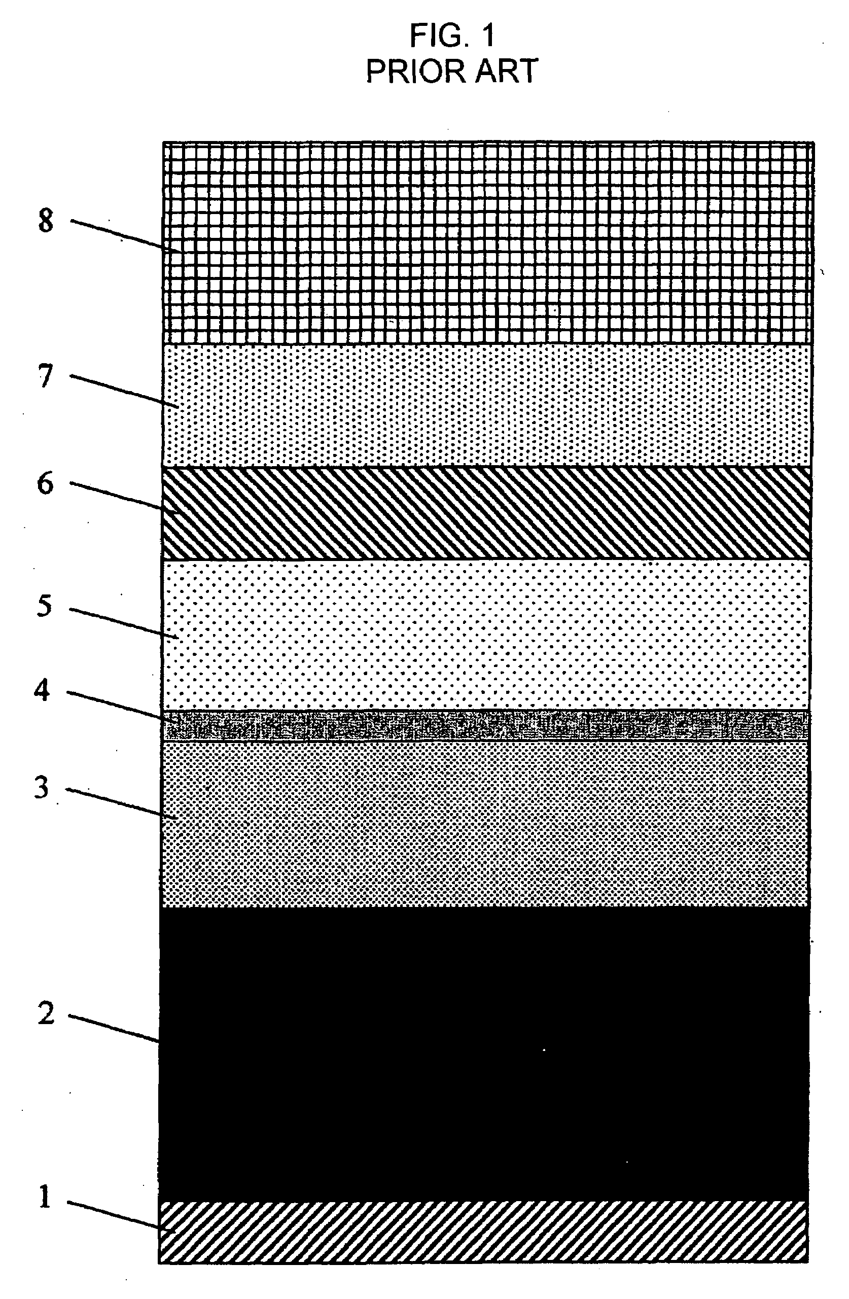
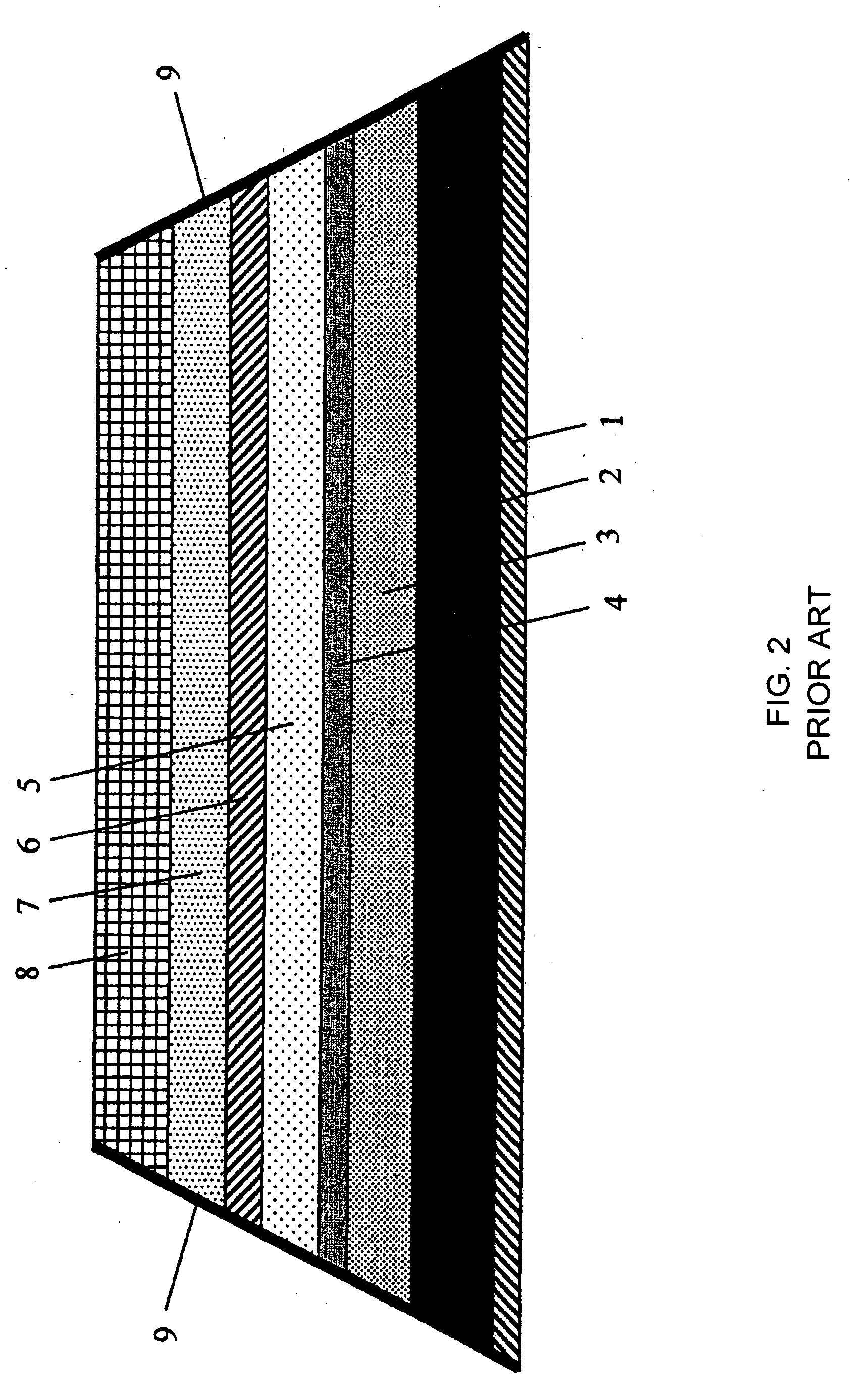
[0031]FIGS. 3(a)-3(d) show a method of manufacturing magnetoresistive elements of the present invention. FIGS. 3(a)-3(d) are cross-sectional views of the magnetoresistive element. As shown in FIG. 3(a), an underlayer 1 of Ta is formed on a substrate 10 made of Al2O3—TiC, and an anti-ferromagnetic layer 2 of Ir—Mn alloy is formed subsequently. Here, the anti-ferromagnetic layer 2 has surface roughness higher than that of the anti-ferromagnetic layer made of Pt—Mn alloy which is generally used. Accordingly, as shown in FIG. 3(b), the first pinned magnetic layer laminated on the Ir—Mn alloy also has higher surface roughness because of the influence of the Ir—Mn alloy as the underlayer.

[0032]Thereafter, the surface of the first pinned magnetic layer is smoothed with the gas cluster ion beam or inverse sputtering method as shown in FIG. 3(c). Next, as shown in FIG. 3(d), a non-magnetic intermediate layer 4 of Ru, a second pinned magnetic layer 5 of Co—Fe alloy, a tunnel barrier layer 6 o...

second embodiment

[0033]When the tunnel magnetoresistive element of the present invention is used in the magnetic head, the tunnel magnetoresistive element is laminated, for example, after an insulating layer made of Al2O3 and a shield layer of NiFe are laminated on Al2O3—TiC of the substrate. This is also true in the

[0034]When Al2O3 is used for the tunnel barrier layer, any influence is applied on the magnetoresistive characteristic thereof, even if the second pinned magnetic layer as the underlayer is smoothed with the gas cluster ion beam or inverse sputtering method, because Al2O3 forms an amorphous layer. However, when MgO is used as the tunnel barrier layer, excellent magnetoresistive characteristics cannot be obtained when the second pinned magnetic layer is used as the underlayer and is smoothed with the gas cluster ion beam or inverse sputtering method, because the crystal layer and crystal structure of MgO is important to obtain excellent magnetoresistive characteristics.

[0035]However, acco...


PUM


Abstract

Stable anti-ferromagnetic exchange coupling can be obtained between a first pinned magnetic layer in a magnetoresistive element and a second pinned magnetic layer through smoothing of a non-magnetic intermediate layer, by smoothing the first pinned magnetic layer. The magnetoresistive element is made by sequentially laminating an underlayer, an anti-ferromagnetic layer, the first pinned magnetic layer, the non-magnetic intermediate layer, the second pinned magnetic layer, a tunnel barrier layer, a free magnetic layer, and a protection layer. The first pinned magnetic layer is smoothed before the non-magnetic intermediate layer is laminated over the first pinned magnetic layer. Stable magnetoresistive characteristics can be obtained, even when thickness is reduced, by smoothing the tunnel barrier layer. In that case, excellent magnetoresistive characteristics can also be obtained even when the tunnel barrier layer requires crystal properties.

Description

[0001]The present invention relates to a tunnel magneto-resistive element and a manufacturing method thereof, and more specifically to a film structure of a tunnel magnetoresistive element.BACKGROUND OF THE INVENTION[0002]To improve hard disk drives (HDD) to have higher capacity and smaller size, a high sensitivity, high output thin film magnetic head is needed. Even the performance characteristics of a gigantic magnetoresistive (GMR) element must be further improved. To this end, development of a tunnel magnetoresistive (TMR) element, which is expected to provide a resistance changing rate of two times or more the rate of the GMR element, is continuing.[0003]A film structure of a convention tunnel magnetoresistive element is shown in FIG. 1. The tunnel magnetoresistive element has an underlayer 1, an anti-ferromagnetic layer 2, a first pinned magnetic layer 3 pinned with an exchange coupling force from the anti-ferromagnetic layer 2, a non-magnetic layer 4, a second pinned magnetic...

Claims


Application Information

Patent Timeline
IPC IPC(8): G11B5/33
CPCB82Y10/00B82Y25/00B82Y40/00G01R33/093G01R33/098G11B5/3163H01L43/12G11B5/3909G11B5/398H01F10/3254H01F10/3281H01F41/303H01L43/08G11B5/3906H10N50/01H10N50/10G11B5/39H01L27/105H01F10/32
Inventor KOMAGAKI, KOJIRO
Owner FUJITSU LTD
Why Eureka
Try Eureka