
Multifunctional filtration and water purification systems

a multi-functional, water purification technology, applied in the direction of machine/engine, liquid/fluent solid measurement, treatment water, etc., can solve the problems of pyrogens, bacteria, pyrogens, etc., and achieve the effect of not effectively removing particles, pyrogens or bacteria

Inactive Publication Date: 2008-03-27
QUOS
View PDF26 Cites 70 Cited by
  • Summary
  • Abstract
  • Description
  • Claims
  • Application Information

AI Technical Summary

Benefits of technology

[0011] Disclosed is an apparatus for water purification comprising a multi-functional, porous, carbon-based composite electrode comprising a resin (e.g. ion-exchange resin) as a binder, carbon black and / or graphite as active adsorbents, and metal oxides as adsorbent promoters. The porous carbon-based plates may be molded by mixing metal oxides, carbon and / or graphite powders, polymer resin and a bubbling agent, such as ammonium bicarbonate. The resins are cross-linked for stability and the porosity of the resulting electrode plate is more than about 50%, for example, about 50% to about 80%, by volume.

Problems solved by technology

Distillation cannot remove some volatile organics and it consumes large amounts of energy.
However, the resin materials need to be regenerated and changed frequently.
In addition, this method does not effectively remove particles, pyrogens, or bacteria.
Carbon adsorption processes can remove dissolved organics and chlorine with long life and high capacity; however, fine carbon particles are generated during the process due to corrosion.
Micropore membrane filtration, a high cost process, removes all particles and microorganisms greater than the pore size of the membrane; however, it cannot remove dissolved inorganics, pyrogens or colloids.
The ultrafilter is a tough, thin, selectively permeable membrane that retains most macromolecules above a certain size, including colloids, microorganisms, and pyrogens; however, it will not remove dissolved organics.
Reverse osmosis membranes are capable of rejecting all particles, bacteria, and organics; however, the flow rate and productivity are low.
Ultraviolet radiation cannot remove ionized inorganics.
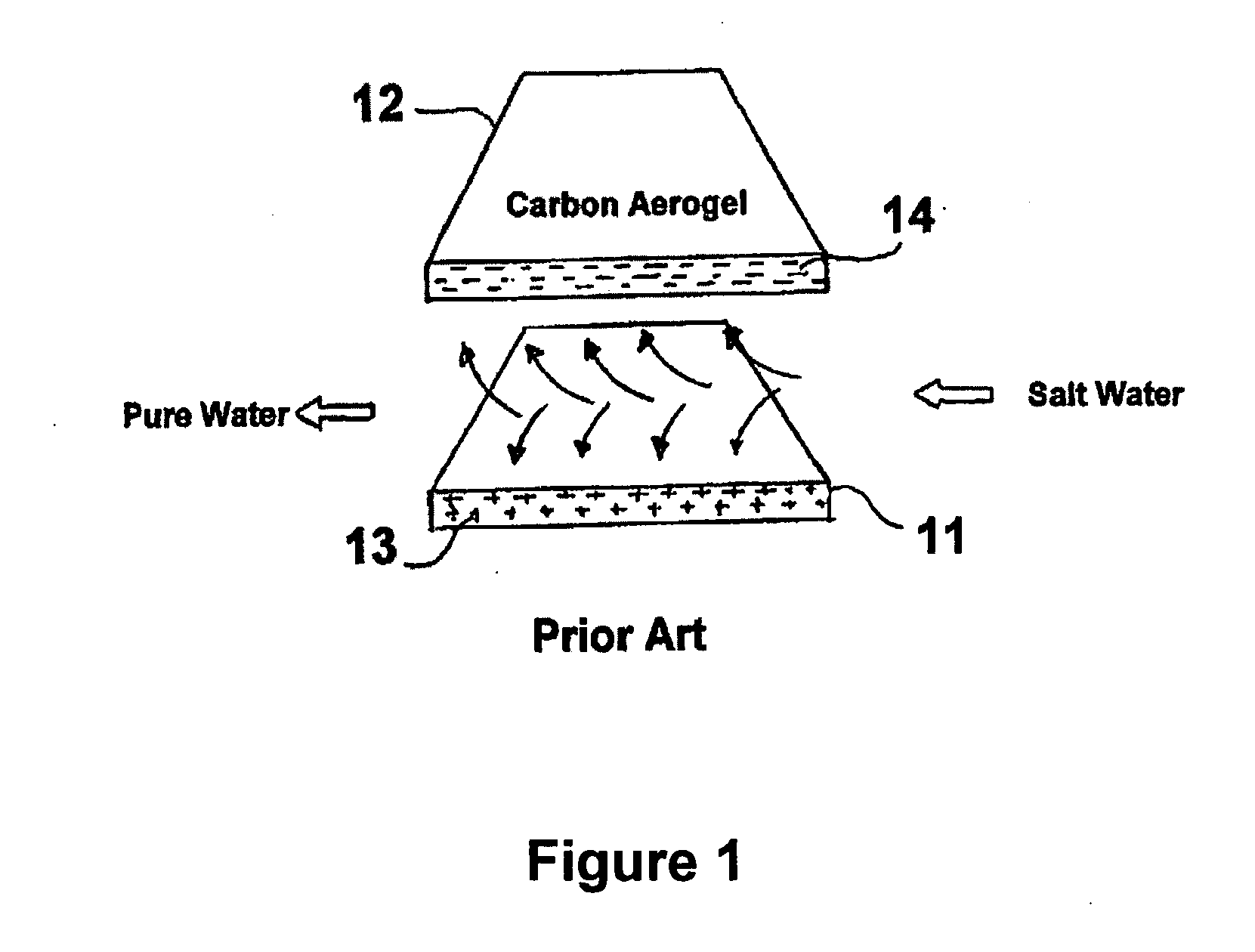
The main problem with this method is that the electrosorption capacity (salt removal) decreases with cycle life.
However, the interface between the active carbon and the aerogel diminishes, reducing the actual electrode active area.
In addition, capacitive deionization requires aggressive pre-filtration and cannot remove non-ionic species.
However, by virtue of the serpentine flow arrangement between the electrode plates, the useful area for the electrodes is limited to the electrode surface.

Method used


Image

  • Multifunctional filtration and water purification systems
  • Multifunctional filtration and water purification systems
  • Multifunctional filtration and water purification systems

Examples


example 1

Production of Exfoliated Graphite

[0091] Exfoliated graphite was produced by mixing concentrated sulfuric acid and graphite powders. The mixture was heated in an oven at 600° to 1000° C. The resulting expanded graphite includes C═O and C—OH bonds on the graphite particles, which crosslink with poly(ethylene vinyl alcohol) and glutaraldehyde. The resulting graphite powders are stable in the porous plate and can not wash out during the wastewater treatment process.

example 2

Production of Porous Graphite Electrode

[0092] 9 grams of exfoliated graphite powders were mixed with 10 grams of water and 10 grams of 10 wt % polyvinyl alcohol), forming a first mixture. 10 grams of water were mixed with 2 grams of 50 wt % glutaraldehyde in water and 0.5 ml HCl (35 wt %), forming a second mixture. The two mixtures were mixed together thoroughly and the resulting mixture was cast to produce a 1 / 16″ thick sheet which was then heat treated at 100° C. Water boiling from the plate generated bubbles, making the plate porous. Because glutaraldehyde binds with poly(vinyl alcohol) in an irreversible fashion, the resulting cross-linked polymer was entirely insoluble, even in hot water. In some experiments, PEVA was used as a binder to increase the electrode strength. The solvent for PEVA was 1:1 volume ratio of 1-propanol and water.

[0093] Table 1 shows a comparison of surface resistance between the electrode produced in accordance with this example and other electrode mate...

example 3

Variation of Electrode Porosity by using Different Bubble Agents

[0094] Two graphite-based porous electrodes were produced using different bubble agents. 8 grams of exfoliated graphite powder and 1 gram of bubble agent (ammonium bicarbonate or sodium bicarbonate) were mixed with 10 grams of water and 10 grams of 10 wt % polyvinyl alcohol, forming a first mixture. 10 grams of water were mixed with 2 grams of 50 wt % glutaraldehyde and 1.5 ml HCl (35 wt %), forming a second mixture. The two mixtures were mixed thoroughly and the resulting mixture was cast to produce a 1 / 16 in thick sheet. The sheet was cured at room temperature. Since glutaraldehyde binds with polyvinyl alcohol in an irreversible fashion, the resulting cross-linked polymer was insoluble, even in hot water.

[0095] Electrodes produced with or without bubble agent were produced as described in Example 2 and tested in a system without applied water pressure. An electrode produced with no bubble agent had low water permeab...


PUM

PropertyMeasurementUnit
Diameteraaaaaaaaaa
Fractionaaaaaaaaaa
Fractionaaaaaaaaaa

Abstract

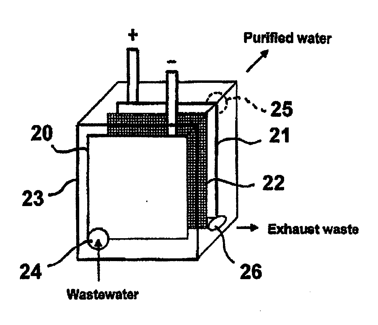
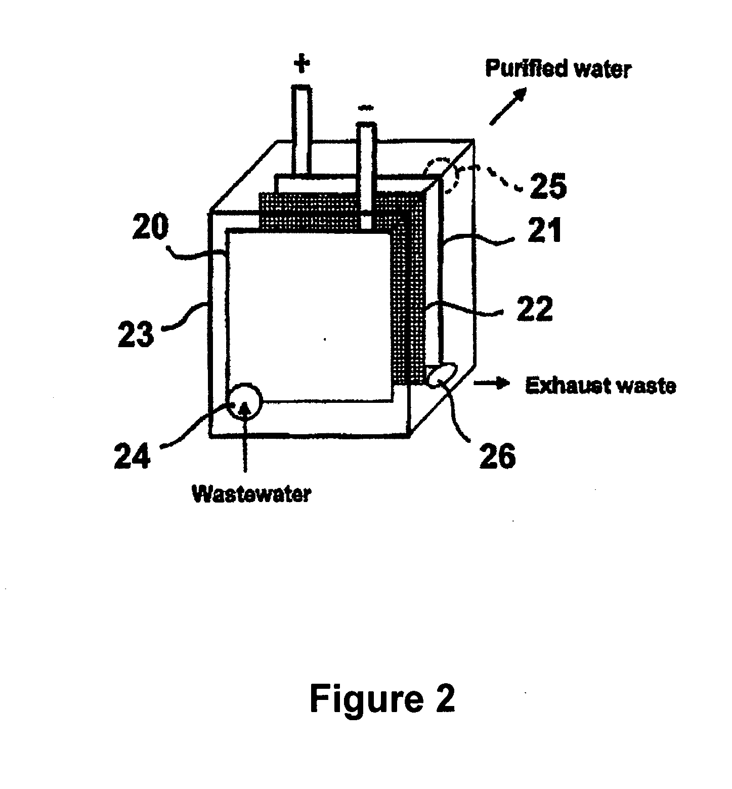
A water purification system having a porous anode electrode (21) and a porous cathode electrode (20), each of which is made of graphite, at least one metal oxide, and an ion-exchange, cross-linked, polarizable polymer, and optionally comprises microchannels. Disposed between the electrodes is a non-electron conductive, fluid permeable separator element (22), whereby wastewater is able to flow from one electrode to the other electrode. The electrodes and separator may be disposed within a housing (23) having a wastewater inlet opening (24), and exhaust waste outlet opening (26) and a purified water outlet opening (25). In this way, components of the system are easily replaced should the need arise.

Description

CROSS-REFERENCE TO RELATED APPLICATIONS [0001] This application is a continuation-in-part of U.S. patent application Ser. No. 11 / 724,534, filed on Mar. 14, 2007, which is a continuation-in-part of U.S. patent application Ser. No. 11 / 515,544, filed on Sep. 5, 2006, which is a continuation-in-part of U.S. patent application Ser. No. 11 / 497,092, filed on Aug. 1, 2006, which claims priority benefit of U.S. Provisional Application No. 60 / 794,287, filed Apr. 21, 2006. This application is related to the PCT International Application entitled “Multifunctional Filtration and Water Purification Systems” by inventors Qinbai Fan, Jeremy R. Chervinko, and Renxuan Liu filed concurrently with the present application. The entire contents of those applications are herby incorporated by reference herein.BACKGROUND OF THE INVENTION [0002] 1. Field of the Invention [0003] This invention relates to an apparatus for water purification. More particularly, this invention relates to a multi-functional appar...

Claims


Application Information

Patent Timeline
IPC IPC(8): C02F1/46
CPCC02F1/42C02F1/46109C02F1/4691C02F2201/46115C02F2103/08C02F2103/10C02F2103/365C02F2001/46161
Inventor FAN, QINBAICHERVINKO, JEREMY R.LIU, RENXUAN
Owner QUOS
Learn More