
Method for production of metal foam or metal-composite bodies

a technology of metal foam and metal composite body, which is applied in the field of powder metallurgy, can solve the problems of limited possibility of production of semi-finished products, low method output, and inability to heat the material economically, and achieves high specific strength and rigidity

Inactive Publication Date: 2008-03-27
AGS TARON INVESTMENTS INC
View PDF25 Cites 2 Cited by
  • Summary
  • Abstract
  • Description
  • Claims
  • Application Information

AI Technical Summary

Benefits of technology

This method significantly increases product yield, reduces manufacturing costs, broadens the range of product sizes and properties, and provides lightweight, stiff, energy-absorbing, and sound-insulating materials with environmental benefits.

Problems solved by technology

In addition, this method demonstrates a very low output because of the prolonged heating of the large size press container filled with the powder mixture.
Even in the case where the powder mixture would be heated in a container having 100 mm in diameter and 400 mm in height, the heating operation would be economically not feasible.
The disadvantages of these techniques are the limited possibility of production of semi-finished products, especially sheets of commercial sizes, low product yield and output, high manufacturing cost.

Method used


Image

  • Method for production of metal foam or metal-composite bodies
  • Method for production of metal foam or metal-composite bodies
  • Method for production of metal foam or metal-composite bodies

Examples


example 1

[0082]The example of the realization of the method for production of dense foamable chips is as follows.

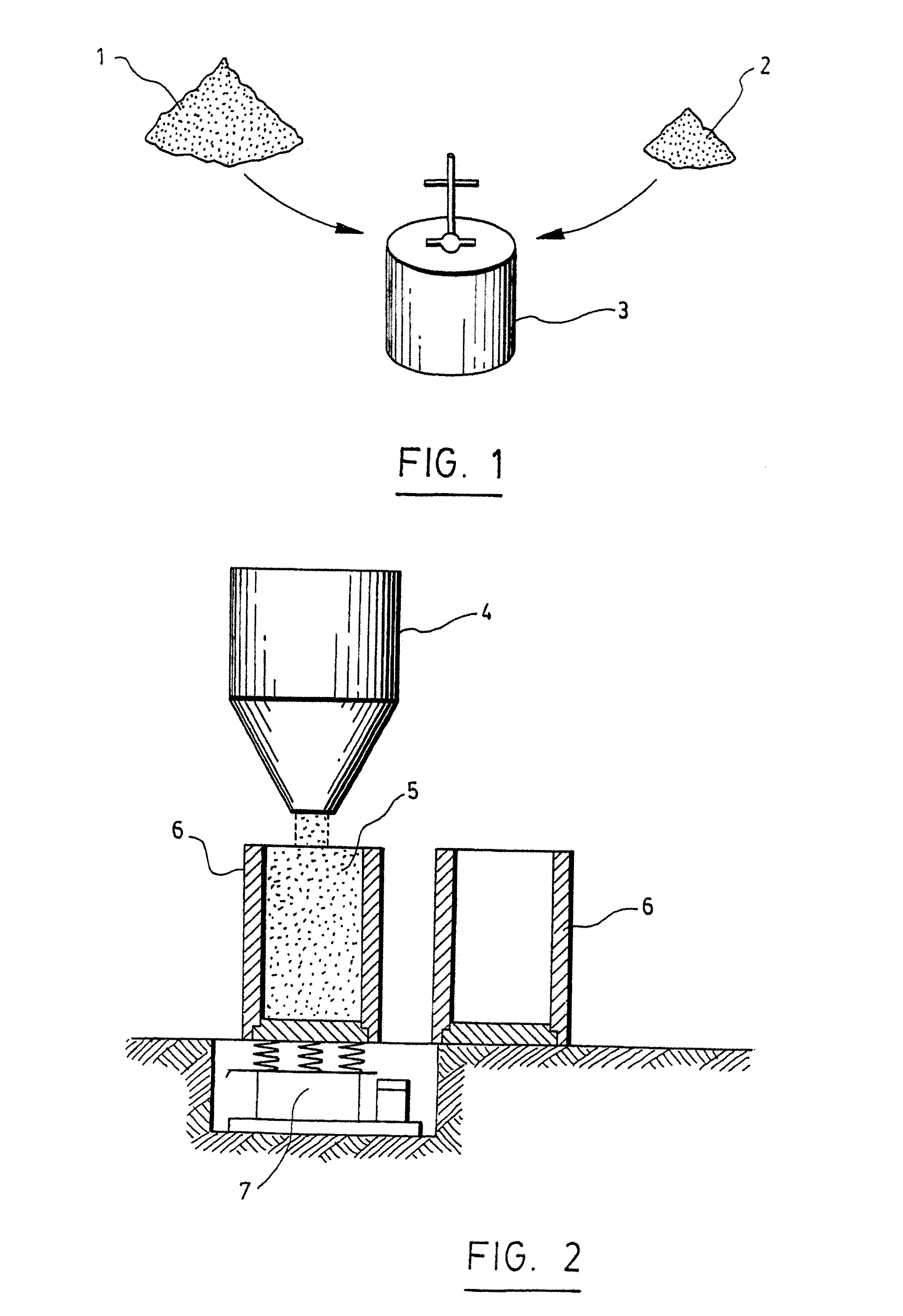
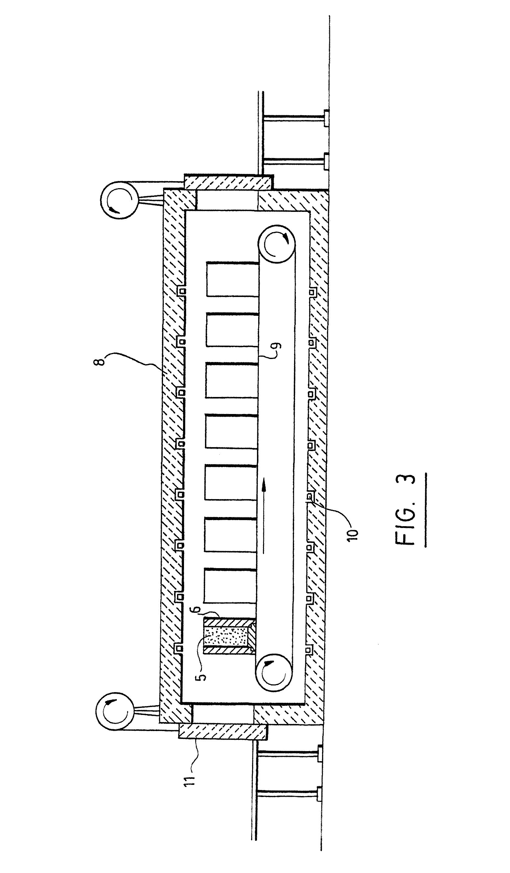
[0083]Al—Mg—Cu—Mn aluminum alloy powder (a liquidus temperature of the alloy is 640-645° C., a temperature of low-melting point eutectic is 505° C.) of 300 kg in weight was mixed with TiH2 foaming agent of 3.25 kg in weight (a decomposition temperature is 690° C. and filled in a split mould of 340 mm diameter, 800 mm in height with internal space of 290 mm in diameter. FIG. 8 shows a vertical cross section of the phase diagram of Al—Mg—Cu—Mn alloys. Hatched zone in this figure represents alloys used in the process. As can be appreciated, the average solidus temperature is 503° C. and the liquidus temperature is approximately 650° C. The powder mixture was compacted by vibration to obtain a density of 1.75-1.8 g / cm3. Weight of the mixture in each mould was from 97 up to 100 kg. The powder mixture was heated at a temperature of 510-515° C. to ensure liquid-phase sintering after cool...

example 2

[0087]The example of realization of the method for production of porous semi-finished pellets from the foamable chips is as follows:

[0088]Al—Zn—Cu—Mg aluminum alloys powder (a liquidus temperature of the alloy is 630-640° C., a temperature of low-melting point eutectic formation is 480° C. of 210 kg in weight was mixed with CaCO3 foaming agent of 12 kg in weight (a decomposition temperature is 720° C.) and filled in a split mould of 340 mm in diameter, 800 mm in height with internal space of 290 mm in diameter. FIG. 9 shows surfaces of crystallization (surfaces of liquidus) of the powder alloy Al—Zn—Cu—Mg containing Zn-4, 5%, Cu 3.5-4.5%, Mg-negligible, Al-balance. The alloys used are in the AL corner of the diagram (small hatched zone) and have a liquidus temperature of 650° C. Solidus of these alloys is in the interval of temperatures of 510-520° C. The powder mixture was compacted by vibration to obtain a density of 1.75-1.8 g / cm3. Weight of the mixture in each mould was from 97 ...

example 3

[0092]An example of the realization of the method for production of flat porous semi-finished products is as follows.

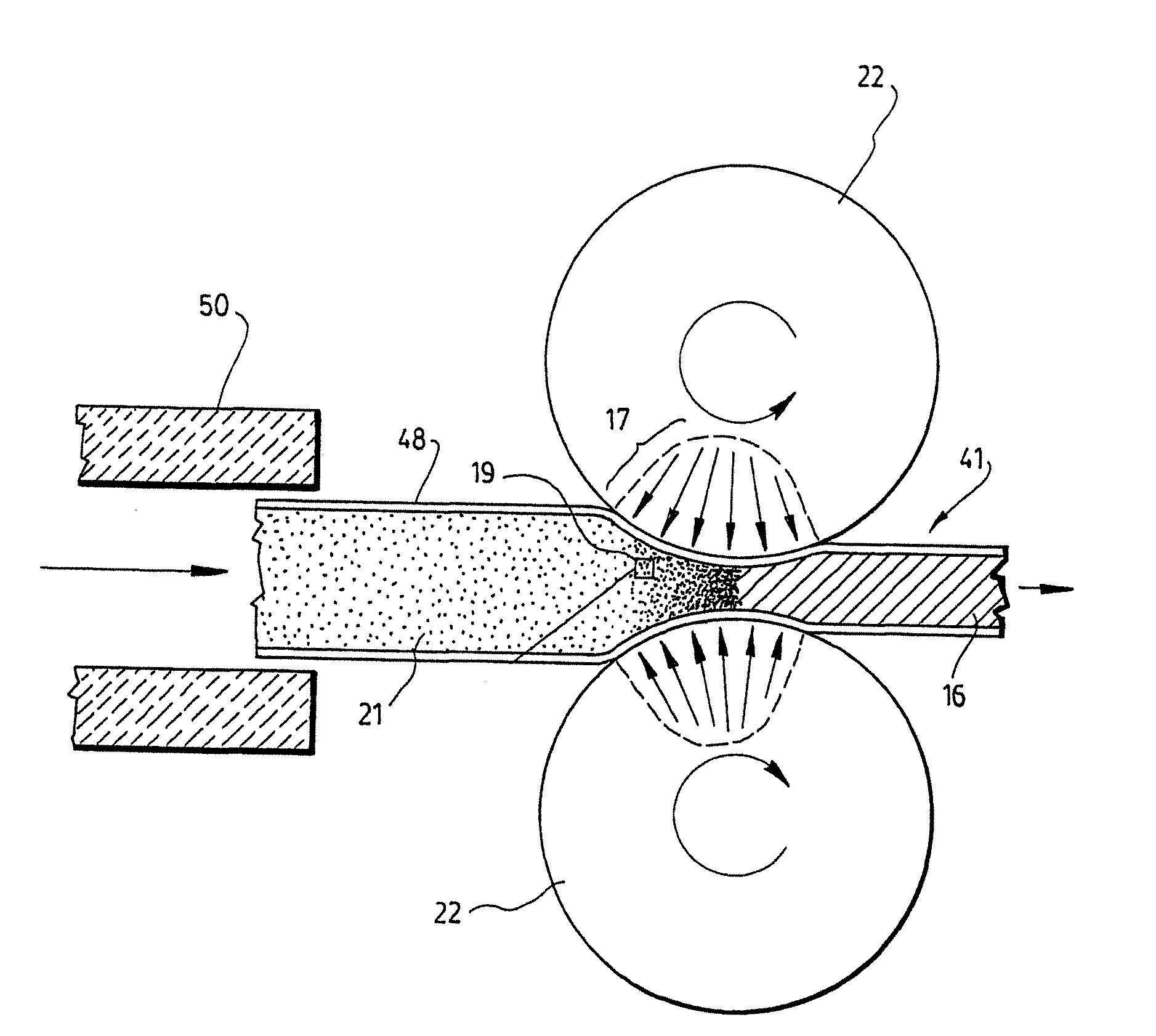
[0093]Al—Mg—Cu—Mn aluminum alloy powder (a liquidus temperature of the alloy is 640-645° C., a temperature of low-melting point eutectic is 505° C.) of 30 kg in weight was mixed with TiH2 foaming agent of 0.32 kg in weight and filled in 10 closed volume metal shells with length 500 mm, width 120 mm and thickness 10 mm. The powder mixture was compacted by vibration and a pass through the straightening machine to obtain a density of 1.8-2.0 g / cm3. Weight of the mixture in each shell was from 2.9 up to 3.2 kg. Then the powder mixture in a shell was heated at a high rate in a furnace to a temperature 515-550° C. and fed on a rolling mill on which 29 kg of 120×1000×5 mm blanks with metal facing and foamable core were rolled. The blanks were used for free foaming of sandwich panels. High-temperature heat treatment was carried out by heating of the sheet blanks from below on...


PUM


Abstract

A method for the production of foamable or foamed metal pellets, parts and panels. The method comprises the steps of: i) providing a mixture of a metal alloy powder with a foaming agent powder, ii) pre-compacting the mixture of step i); iii) heating the pre-compacted mixture of step ii) to a temperature below a decomposition temperature of the foaming and at which permanent bonding of the particles occurs v) hot compacting the body for producing a compacted body made of a metal matrix embedding the foaming agent; and vi) reducing the compacted body into metal fragments and thereby obtaining dense foamable metal chips. A method for the production of a foam metal using a closed volume metal shell is also disclosed. The method comprises the steps of: a) providing metal pieces and reducing said metal pieces into smaller metal particles; b) mixing the metal particles with an additive having a decomposition temperature that is greater than a solidus temperature of said metal particles; c) pouring the mixture of step b) into a closed volume metal shell having a given thickness and providing the metal shell with at least one passage for gases to escape; d) reducing the thickness of the metal shell by applying pressure; e) heating the metal shell to a temperature above said solidus temperature of the metal particles and below said decomposition temperature of the additive, and immediately applying pressure on the metal shell sufficient to compress the metal particles and to create micro shear conditions between the metal particles so as to obtain a dense metal product.

Description

CROSS-REFERENCE TO RELATED APPLICATIONS[0001]This application is a continuation of U.S. Ser. No. 10 / 619,717 filed on Jul. 15, 2003, which is a continuation of International Patent Application No. PCT / CA02 / 00073 filed on Jan. 16, 2002, which designates the United States and claims priority Application Nos. U.S. 60 / 261,218 filed Jan. 16, 2001, CA 2,332,674 filed Jan. 29, 2001 and CA 2,344,088 filed Apr. 12, 2001. The above-mentioned applications are incorporated herein by reference in their entirety.FIELD OF THE INVENTION[0002]The present invention relates to the field of powder metallurgy. More specifically, it concerns a method of manufacturing foamable metal or metal-composite bodies and their use, particularly as lightweight and stiff material with improved impact, energy, sound absorption and heat retardant properties. It also preferably concerns environmentally friendly and low cost material produced from recycled aluminum alloys or scrap with broad range of chemical composition...

Claims


Application Information

Patent Timeline
Patent Type & Authority Applications(United States)
IPC IPC(8): B32B5/18B22F3/11B22F7/04B22F1/06B22F1/148B22F5/10B22F8/00
CPCB22F1/0007B22F1/0096B22F3/1125B22F8/00Y10T428/12042B22F2998/10B22F2999/00B22F2003/023B22F9/04B22F1/0003B22F3/1208B22F3/14B22F3/18B22F3/20B22F3/02B22F3/1007B22F2201/04Y02W30/50B22F1/148B22F1/06B22F1/12Y02P10/20
Inventor VATCHIANTS, SERGUEI
Owner AGS TARON INVESTMENTS INC
Learn More