Glycol separation and purification

Active Publication Date: 2008-04-03
SHELL OIL CO
View PDF9 Cites 9 Cited by
  • Summary
  • Abstract
  • Description
  • Claims
  • Application Information

AI Technical Summary

Benefits of technology

[0016] Although systems are known, e.g. from U.S. Pat. No. 6,080,897, for the separation of catalyst solution from crude MEG with purification of MEG by sequential distillation typically in two distillation columns, there is no system which operates low pressure separation of catalyst solution from crude MEG with purification of MEG in one column or in a separate MEG purification column and separate upstream catalyst separation vessel, and which also includes flashed glycols feed into the rectification section taking advantage of the generation of MEG vapour in the first separation section for use in the second rectification section without condensing crude MEG after separation and before feeding to the rectification section. This produces a net energy saving and avoids the need for intermediate accumulation and transport equipment for the condensed crude MEG, compared to the known process which operates an intermediate condensation section to enable feed of liquid crude MEG to the higher pressure rectification and stripping section where it is once again vaporised. In addition, this allows the stripping section to handle lower liquid and vapour loading than the liquid and vapour loading of the rectification and pasteurisation sections in the MEG purification column. In a further advantage, the present invention operates without the use of a mechanical transport device b

Problems solved by technology

The disadvantage of this system is that the MEG stream need

Method used


Image

  • Glycol separation and purification
  • Glycol separation and purification
  • Glycol separation and purification

Examples


Embodiment Construction

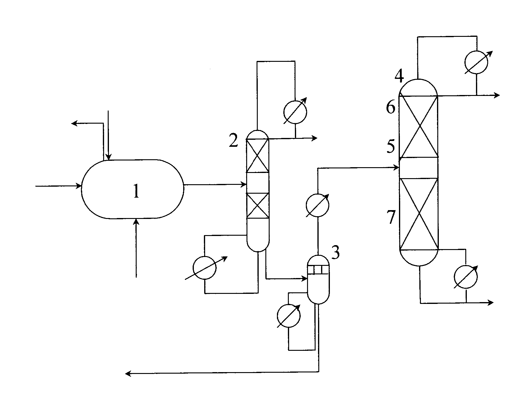
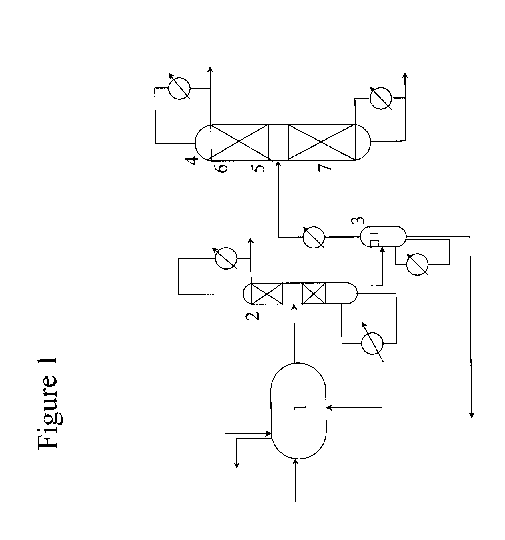
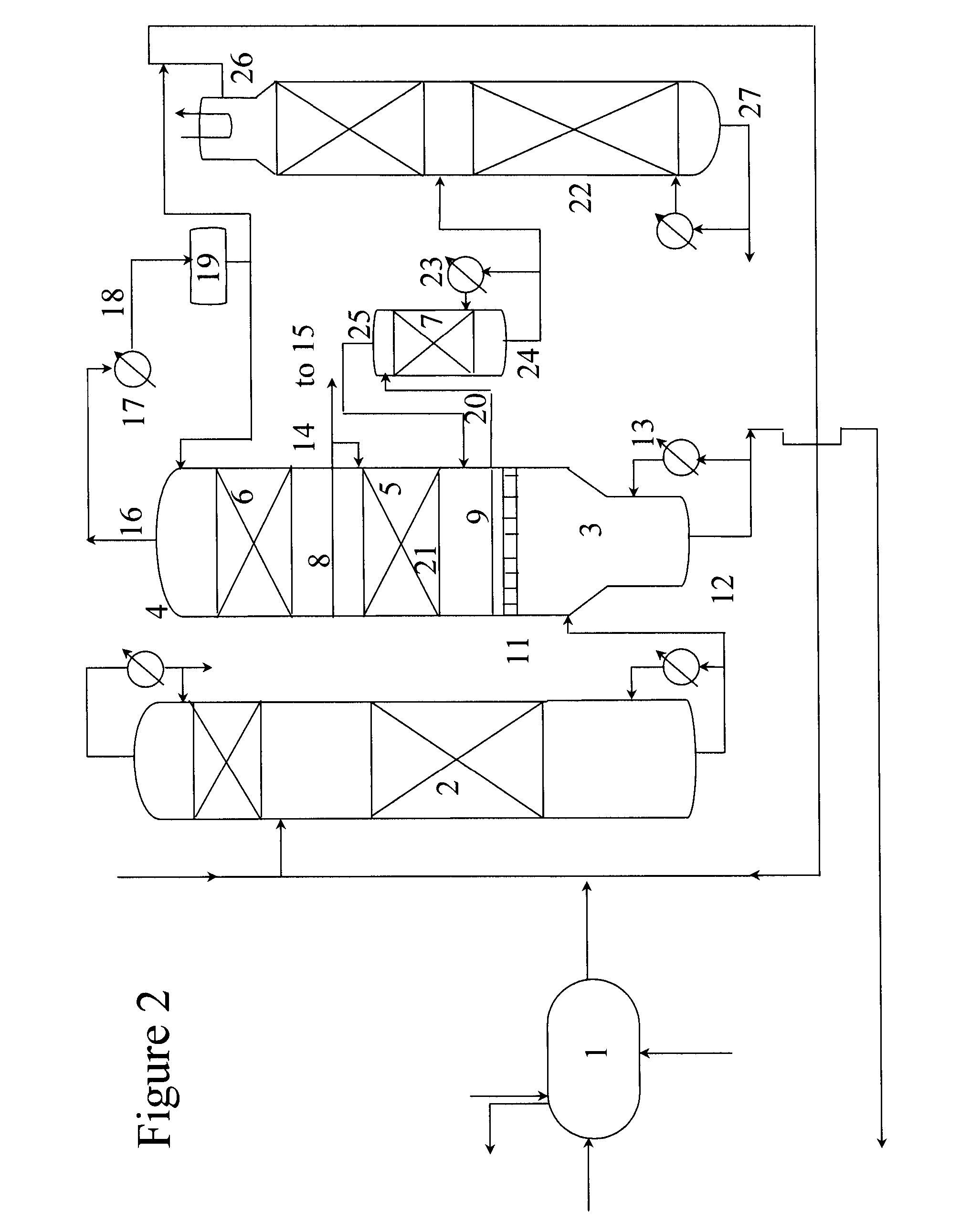
[0020] Typically the process and apparatus of the invention separate catalyst solution derived from a glycol dehydrator section. Catalyst solution is substantially or predominantly liquid phase, although it may include vapour, on entry to the separation section. Catalyst solution comprises catalyst in crude MEG. In the separation section, heat input to a temperature as hereinafter described preferably generates a flash separation of crude MEG whereby vapour phase crude MEG is separated from a solution of greater than 0 wt % to 95 wt % catalyst in crude MEG which is recycled for further use in the EO to MEG conversion reaction. As hereinbefore described, the vapour phase crude MEG is fed to the rectification section where mass transfer between liquid phase and vapour phase confers a rectification, separating MEG as overhead from diethylene glycol (DEG) and higher boiling glycols. Separated MEG rises to a pasteurisation section where further mass transfer between the phases confers a ...


PUM

PropertyMeasurementUnit
Temperatureaaaaaaaaaa
Pressureaaaaaaaaaa

Abstract

A process and an apparatus for the separation of a homogeneous catalyst solution from crude monoethylene glycol (MEG) and for purifying MEG is disclosed. The process comprises separating catalyst solution by evaporating crude MEG and feeding crude MEG to a rectification section, a stripping section, and thence to a pasteurisation section, each section operated at subatmospheric pressure of 0.5×10⁵ Nm−2 or less, the rectification and pasteurisation sections being at pressure less than that of the catalyst separation section, wherein the process provides a pressure differential across the catalyst separation and rectification sections and wherein vapour phase crude MEG from the catalyst separation section is fed as substantially vapour phase feed to the rectification section. The apparatus comprises a catalyst separation section, an MEG rectification section, a stripping section and a pasteurisation section, wherein the MEG rectification and pasteurisation sections are located within a MEG purification column, and the catalyst separation section is either located in the MEG purification column or in a separate upstream vessel, and wherein the separation section provides a crude MEG feed inlet to the MEG rectification section and an outlet for separated catalyst, wherein the crude MEG feed inlet to the MEG rectification section is a vapour feed inlet.

Description

CROSS-REFERENCE TO RELATED APPLICATIONS [0001] This application claims the benefit of European Patent Application No. 06253031.6, filed Jun. 13, 2006, which is incorporated herein by reference. FIELD OF THE INVENTION [0002] The present invention relates to an apparatus and process for separating catalyst from crude monoethylene glycol (MEG) product and purifying MEG; and the use thereof in an ethylene oxide (EO) / ethylene glycol (EG) plant. BACKGROUND OF THE INVENTION [0003] MEG is predominantly used for the manufacture of polyester fibres, polyethylene terephthalate (PET) and, to a lesser extent, in the cooling systems of motor vehicles where it serves as antifreeze. [0004] MEG may be produced by the homogeneously catalysed conversion of EO to EG, directly catalysed by e.g. bicarbonate or metalate salts. Alternatively, MEG may be produced by a 2 step process, a ketal type process (catalysed by acids) or via ethylene carbonate (EC) catalysed by e.g. alkali or alkaline earth metal hal...

Claims


Application Information

Patent Timeline
IPC IPC(8): C07C31/20B01J8/00C07C29/74
CPCB01D3/143C07C29/106C07C29/80C07C31/202C07C31/20
Inventor BASTINGS, ROEL GUILLAUME HUBERTUS LEONARDUSWESTERINK, ANTON PIETER
Owner SHELL OIL CO
Why Eureka
Try Eureka