High-Precision Optical Surface Prepared by Sagging from a Masterpiece

Inactive Publication Date: 2008-05-01
CARL ZEISS SMT GMBH
View PDF5 Cites 46 Cited by
  • Summary
  • Abstract
  • Description
  • Claims
  • Application Information

AI Technical Summary

Benefits of technology

[0053]Using this method extremely precise and very light weight temperature resistant and stiff reflective optical elements may be produced on an industrial scale which may be used e.g. in Wolter type telescopes or as collectors in EUVL systems. Other—possibly thicker—components for EUVL systems which are not nested can be produced by this method in a very cost-effective way on an industrial scale.
[0054]FIG. 1 shows a sketch of an imaging Wolter-type I telescope 1 for focusing beams of incident X-ray radiation into a focal plane 5 arranged perpendicular to an optical axis 4 of the telescope 1. For this purpose, the telescope 1 comprises a plurality of concentrically arranged, rotationally symmetric nested monolithic Wolter-type X-ray mirror shells which are azimuthally segmented. A first and second monolithic Wolter-type mirror segment 2a, 3a of a first mirror shell and a first and second Wolter-type mirror segment 2b, 3b of a second, more i

Problems solved by technology

This leads to very tight requirements with respect to size, mass, and stiffness of the optics.
Effective convection cooling is not possible since these systems are operated in vacuum.
Thus the heat can only be transported by heat conduction and radiative cooling.
Consequently thermally induced problems are increasing due to more and more heat generation.
However, massive mirror segments from more temperature resistant materials are difficult to achieve, due to geometrical restrictions.
The classical way of figuring and finishing to the specified roughness

Method used


Image

  • High-Precision Optical Surface Prepared by Sagging from a Masterpiece
  • High-Precision Optical Surface Prepared by Sagging from a Masterpiece
  • High-Precision Optical Surface Prepared by Sagging from a Masterpiece

Examples


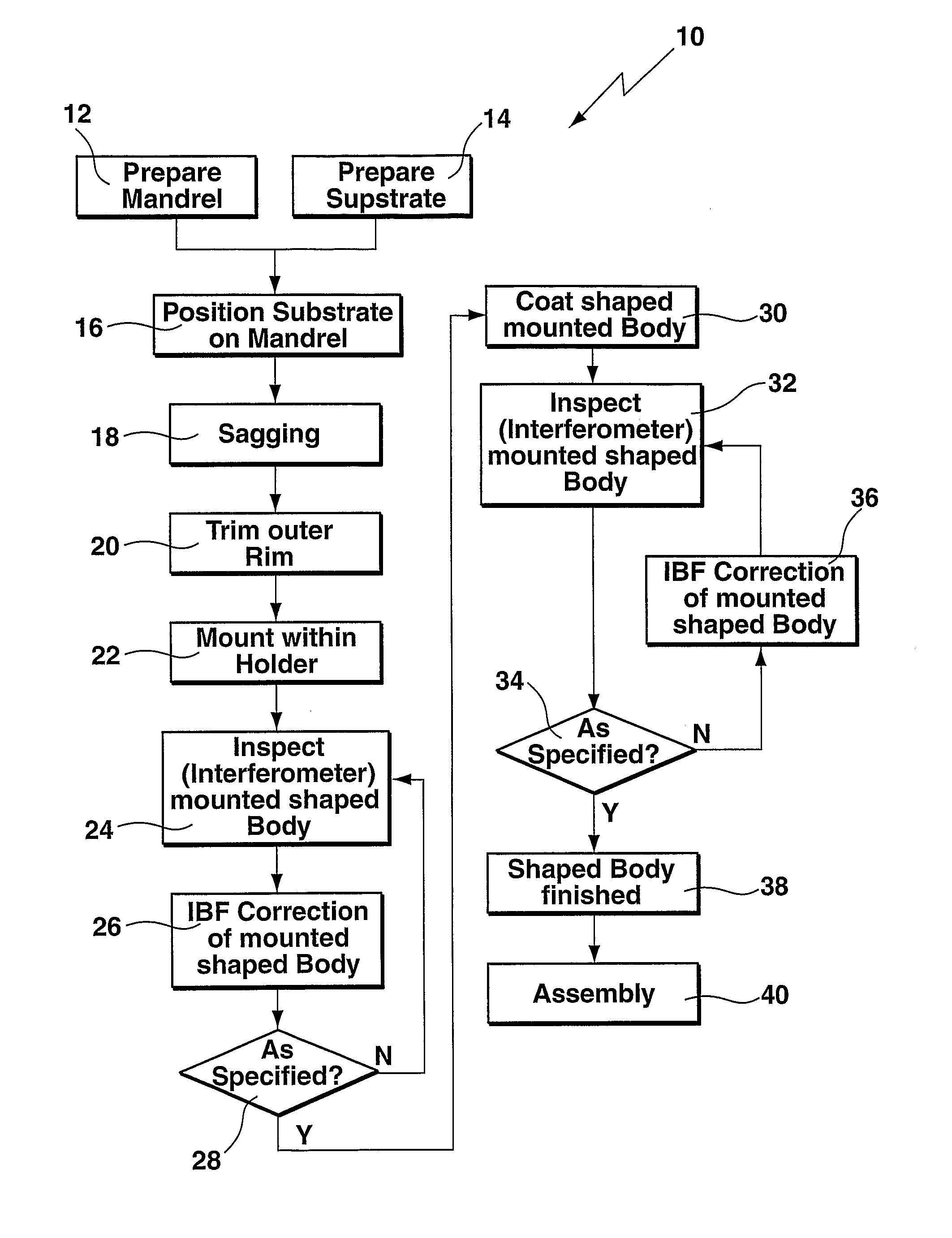
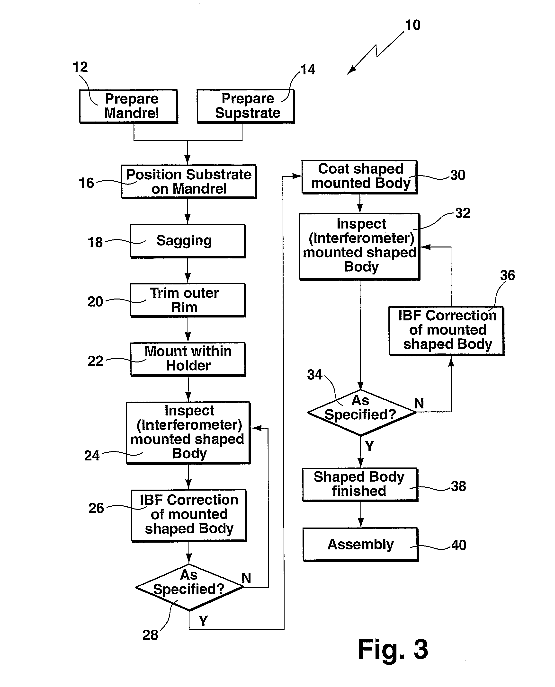
Embodiment Construction

[0058]Various sagging tests were performed using different materials as a mandrel and also as a substrate. Alumina based ceramics, keatite glass ceramic (provided by Schott DESAG AG) and Zerodur® glass ceramic (provided by Schott Glas AG), stainless steel, SiC, Si3N4 were tested as a mandrel material. Substrate materials that are closely matched to the thermal expansion behavior of these mandrels are primarily borosilicate glasses.

[0059]The borosilicate glass D263 (provided by Schott) has a coefficient of thermal expansion (about 7·10−6 / K between 20 and 300° C.) matching an alumina based ceramic. Borofloat® (also provided by Schott) having a lower coefficient of thermal expansion (about 3·10−6 / K) can be used together with keatite mandrels (about 2·10−6 / K). Zerodur® has a coefficient of thermal expansion (on the order of 10−7 / K) which is considerably smaller than the one of all other materials in the relevant temperature range up to 600° C.

[0060]To effect sagging, the temperature was...


PUM

PropertyMeasurementUnit
Thicknessaaaaaaaaaa
Thicknessaaaaaaaaaa
Thicknessaaaaaaaaaa

Abstract

A method of making a high-precision optical surface which may be used either as a Wolter-type segment in an X-ray mirror system or in a collector of a EUVL system or as a spherical, aspherical, or free form normal or grazing incidence mirror in an EUVL system is prepared by sagging a thin flat glass sheet onto a masterpiece, in particular a mandrel, made from a temperature-resistant material, such as an alumina based ceramic or a keatite glass ceramic. The glass sheet is polished to the desired surface roughness (14), is positioned to an upper surface of the masterpiece (16), and is heated (18) to effect sagging onto the upper surface of the masterpiece for generating a shaped body. Thereafter, the shaped body is cooled and removed from the masterpiece, is mounted within a holder (22), is inspected for deviations from the specification (24) preferably using interferometric measurements, and is corrected for defects (26), preferably using ion beam figuring.

Description

BACKGROUND OF THE INVENTION[0001]The invention is directed to the manufacture of a high-precision optical surface. More particularly the invention is directed to a method of making a high-precision optical surface, preferably intended for the use in the EUV and x-ray range, prepared by sagging from a masterpiece, in the following also called a mandrel. Such high-precision optical surfaces are commonly used as reflecting mirror elements e.g. designed in the so-called Wolter-type reflective surfaces (Hans Wolter, Ann. Ph. 6 (1952), 94 pp). However, in general, arbitrarily formed surfaces my be replicated by sagging.[0002]In imaging Wolter-type telescopes the X-ray mirrors are operated at grazing incidence while taking advantage of the physical effect of total reflection. Typical x-ray energies are in the range of 1-10 keV. Usually a Wolter type configuration is provided by consecutively arranging a paraboloid or ellipsoid and a hyperboloid (T. Saha, Appl. Optics 26 (1987), 658 pp). In...

Claims


Application Information

Patent Timeline
IPC IPC(8): B29D11/00
CPCG03F7/70166G03F7/70175G03F7/70958C03B23/0357G21K2201/067C03B23/0252G21K1/06
Inventor EGLE, WILHELMDINGER, UDOMATTHES, AXEL
Owner CARL ZEISS SMT GMBH
Why Eureka
Try Eureka