Optical Compensation Film, Method of Producing the Same, and Polarizing Plate and Liquid Crystal Display Device Using the Same

a technology of optical compensation film and polarizing plate, which is applied in the direction of polarising elements, thin material processing, instruments, etc., can solve the problem that it is difficult to obtain desirable viewing angle characteristics

Active Publication Date: 2008-05-15
FUJIFILM CORP
View PDF18 Cites 17 Cited by
  • Summary
  • Abstract
  • Description
  • Claims
  • Application Information

AI Technical Summary

Problems solved by technology

It has, however, been difficult to obtain desirable viewing angle characteristics, simply by controlling ever-known parameters as described in these publications.

Method used


Image

  • Optical Compensation Film, Method of Producing the Same, and Polarizing Plate and Liquid Crystal Display Device Using the Same
  • Optical Compensation Film, Method of Producing the Same, and Polarizing Plate and Liquid Crystal Display Device Using the Same
  • Optical Compensation Film, Method of Producing the Same, and Polarizing Plate and Liquid Crystal Display Device Using the Same

Examples


example 1

Preparation of Optical Compensation Film (Samples 001 to 010)

[0219]Individual ingredients of a cellulose acetate solution composition, shown below, were placed into a mixing tank, stirred under heating so as to dissolve them, to thereby prepare a cellulose acetate solution.

(Composition of Cellulose Acetate Solution)Cellulose acetate, degree of acetylation 60.9%83 parts by massCellulose acetate, degree of acetylation 55.0%17 parts by massTriphenyl phosphate (plasticizer)7.8 parts by mass Biphenyl diphenyl phosphate (plasticizer)3.9 parts by mass Methylene chloride (first solvent)318 parts by mass Methanol (second solvent)47 parts by mass

[0220]In a separate mixing tank, 16 parts by mass of retardation enhancer shown below, 0.1 to 32 parts by mass of dispersion adjusting agent UV-102 shown below, 87 parts by mass of methylene chloride and 13 parts by mass of methanol were placed, stirred under heating, to thereby prepare a retardation controlling agent solution.

[0221]Thirty-six parts b...

example 2

Preparation of Polarizing Plate

[0235]A stretched polyvinyl alcohol film was allowed for absorption of iodine to thereby manufacture the polarizing film, and the optical compensation film (Sample 001) produced in Example 1 was bonded to one surface of the polarizing film, using a polyvinyl alcohol-base adhesive. The transmission axis of the polarizing film and the slow axis of the retardation plate were aligned in parallel with each other.

[0236]A commercially-available cellulose triacetate film (Fujitac TD80UF, from FUJIFILM Corporation) was saponified, and bonded on the opposite side of the polarizing film, using a polyvinyl alcohol-base adhesive. The polarizing plate was thus produced.

[0237]Polarizing plates were similarly produced except that Sample 001 was replaced respectively with sample 002 to sample 011.

example 3

On-Device Evaluation in Liquid Crystal Display Device

(Production of Bend-Aligned Liquid Crystal Cell)

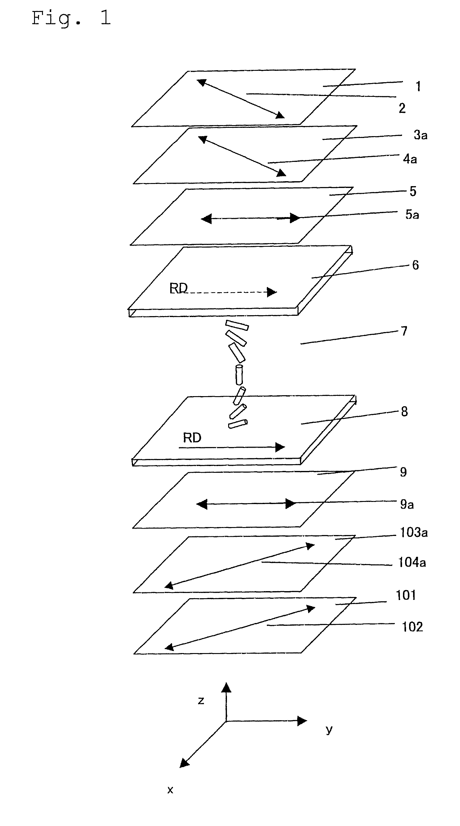
[0238]A polyimide film was provided as an alignment layer to a glass substrate having ITO electrodes formed thereon, and the alignment layer was rubbed. Two thus-obtained glass substrates were opposed so as to align the direction of rubbing in parallel with each other, and the cell gap was adjusted to 4.0 μm. A liquid crystalline compound (ZLI1132, from MERCK) having Δn of 0.1396 was injected into the gap, to thereby produce a bend-aligned liquid crystal cell.

[0239]Two produced polarizing plates were bonded to the bend-aligned cell so as to hold it in between, while making the optically anisotropic layers of the polarizing plates contacted with the cell substrates, and making the direction of rubbing of the liquid crystal cell aligned anti-parallel to the direction of rubbing of the optically anisotropic layer contacted therewith.

[0240]A rectangular wave voltage of 55 Hz was applied ...


PUM

PropertyMeasurementUnit
viscosityaaaaaaaaaa
optically anisotropicaaaaaaaaaa
wavelength-dependence α2aaaaaaaaaa

Abstract

A liquid crystal display showing a high contrast and reduced in color shift depending on the viewing angle is provided.
The liquid crystal display device comprises a liquid crystal cell having a retardation value Re1(400) at 400 nm and a retardation value Re1(550) at 500 nm in the black state; and at least one layer of optically anisotropic layer formed of a composition comprising at least one species of liquid crystalline compound, having a retardations value Re2(400) at 400 nm and a retardation value Re2(550) at 550 nm,
    • wherein Re2(400) and Re2(550) of said optically anisotropic layer, and retardations values Re1(400) and Re1(550) satisfy the relational expression (1) below:
0.9≦α2/α1≦1.1   Relational Expression (1)
    • where, α1=Re1(400)/Re1(550) and α2=Re2(400)/Re2(550).

Description

TECHNICAL FIELD[0001]The present invention relates to an optical compensation film, a method of producing the same, a polarizing plate and a liquid crystal display device using the same.BACKGROUND ART[0002]A liquid crystal display device comprises a liquid crystal cell and polarizing plate(s). A polarizing plate comprises protective film(s) generally composed of cellulose acetate, and a polarizing film, and is obtained typically by dying the polarizing film composed of polyvinyl alcohol film with iodine, stretching, and being stacked on both surfaces thereof with protective film(s). A transmission-type liquid crystal display device generally comprises two polarizing plates disposed both sides of the liquid crystal cell, and further comprises one or more optical compensation films; whereas a reflection-type liquid crystal display device generally comprises a reflection plate, a liquid crystal cell, one or more optical compensation film(s), and a polarizing plate in this order. A liqu...

Claims


Application Information

Patent Timeline
Patent Type & Authority Applications(United States)
IPC IPC(8): G02B5/30G02F1/1335
CPCG02B5/3016G02F1/13363G02F2001/133633G02F2001/133637Y10T428/1036G02F2413/04Y10T428/1041Y10T428/10G02F2203/05C09K2323/031C09K2323/03C09K2323/00G02F1/133633G02F1/133637
Inventor IKEDA, AKIRANAGAI, MICHIONISHIKAWA, HIDEYUKI
Owner FUJIFILM CORP
Why Eureka
Try Eureka