Appliances with brushless motors

a brushless motor and motor technology, applied in the direction of mechanical energy handling, cooling/ventilation arrangement, association for rectification, etc., can solve the problems of limited set and use of brushless motors, and achieve the effects of low wattage, high operating voltage, and low operating temperatur

Inactive Publication Date: 2008-05-22
CONAIR CORP
View PDF8 Cites 39 Cited by
  • Summary
  • Abstract
  • Description
  • Claims
  • Application Information

AI Technical Summary

Benefits of technology

[0007]According to an embodiment of the present invention, using a hand held hair dryer as an example, a brushless motor is positioned inside the housing of the hair dryer. The brushless motor has a stator with an array of electromagnetic coils / windings, a rotor mounted for rotation relative to the stator and spaced from the stator in a non-contact fashion, and a plurality of magnets positioned to interact with the coils. A control circuit communicates with the coils to energize them in a sequence that causes the rotor to rotate, thereby spinning an output shaft. The motor output shaft is connected to a primary fan assembly for driving air past a heater element and out of the hair dryer. A secondary fan assembly and / or an air scoop are provided to redirect air towards the motor to maintain a cool operating temperature. The control circuit and the motor coil windings are designed to run the appliance at a relatively low current to accommodate a higher operating voltage. By achieving a low wattage in this manner, it is possible to provide the ability to quickly and selectively provide a non-heated air output interrupting the heated air output, sometimes referred to as a “cool shot” in the hair dryer industry.
[0008]In comparison to standard, known hair dryers and other appliances that use brush contact motors, appliances according to the present invention have the advantage of operating with significantly higher torque and velocity, and operating more efficiently and for longer life cycles.

Problems solved by technology

Brushless electrical motors have been used in recent years in a very limited set of applications including, most notably, in the field of radio controlled model airplanes.
Relatively high costs and cooling challenges, due to higher velocities, have thus far prohibited use beyond specialized industries such as radio controlled model airplanes, where airflow from the movement of the airplane addresses the cooling issues and the high costs are tolerated in hobby and specialized industries.

Method used


Image

  • Appliances with brushless motors
  • Appliances with brushless motors
  • Appliances with brushless motors

Examples


first embodiment

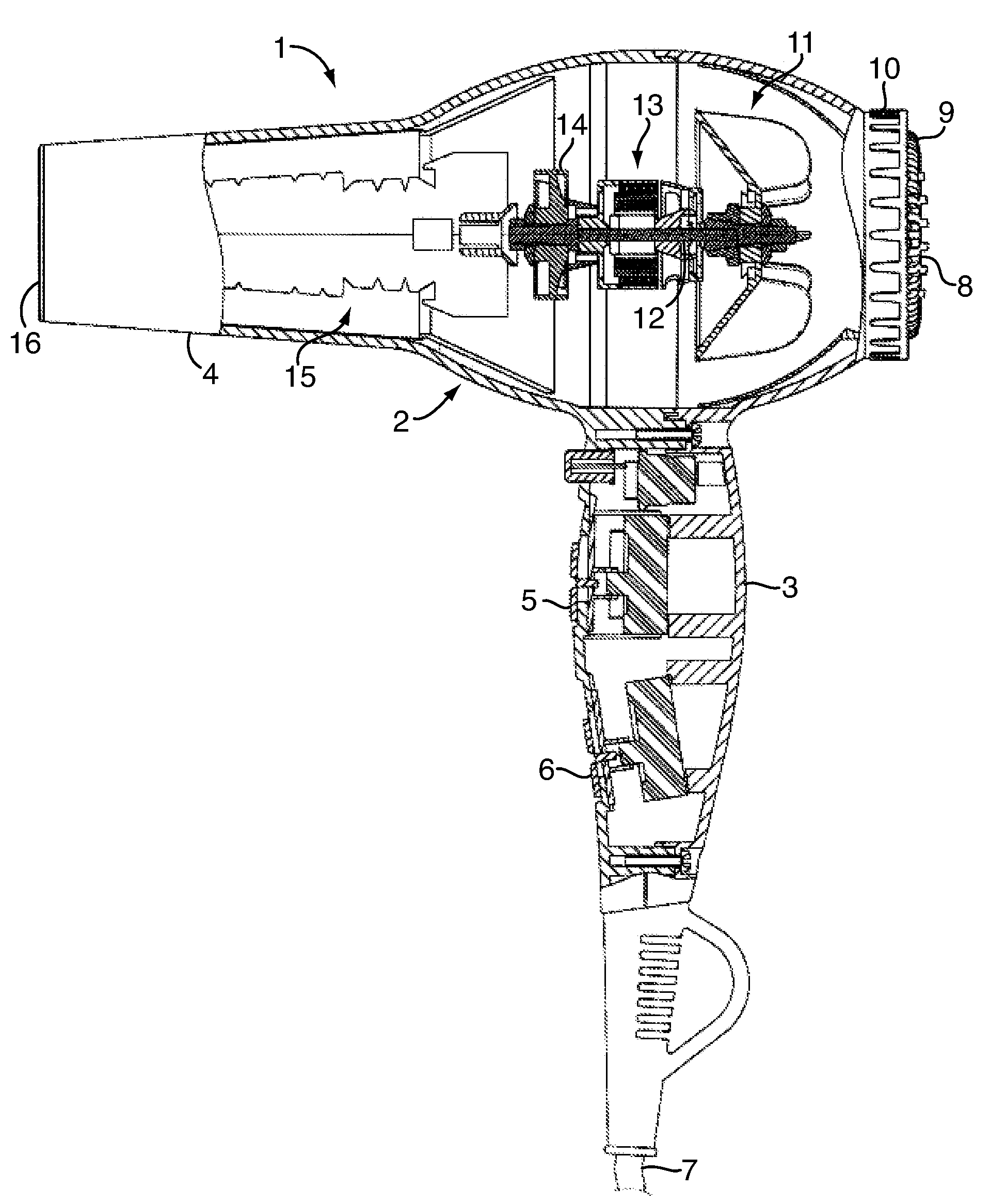
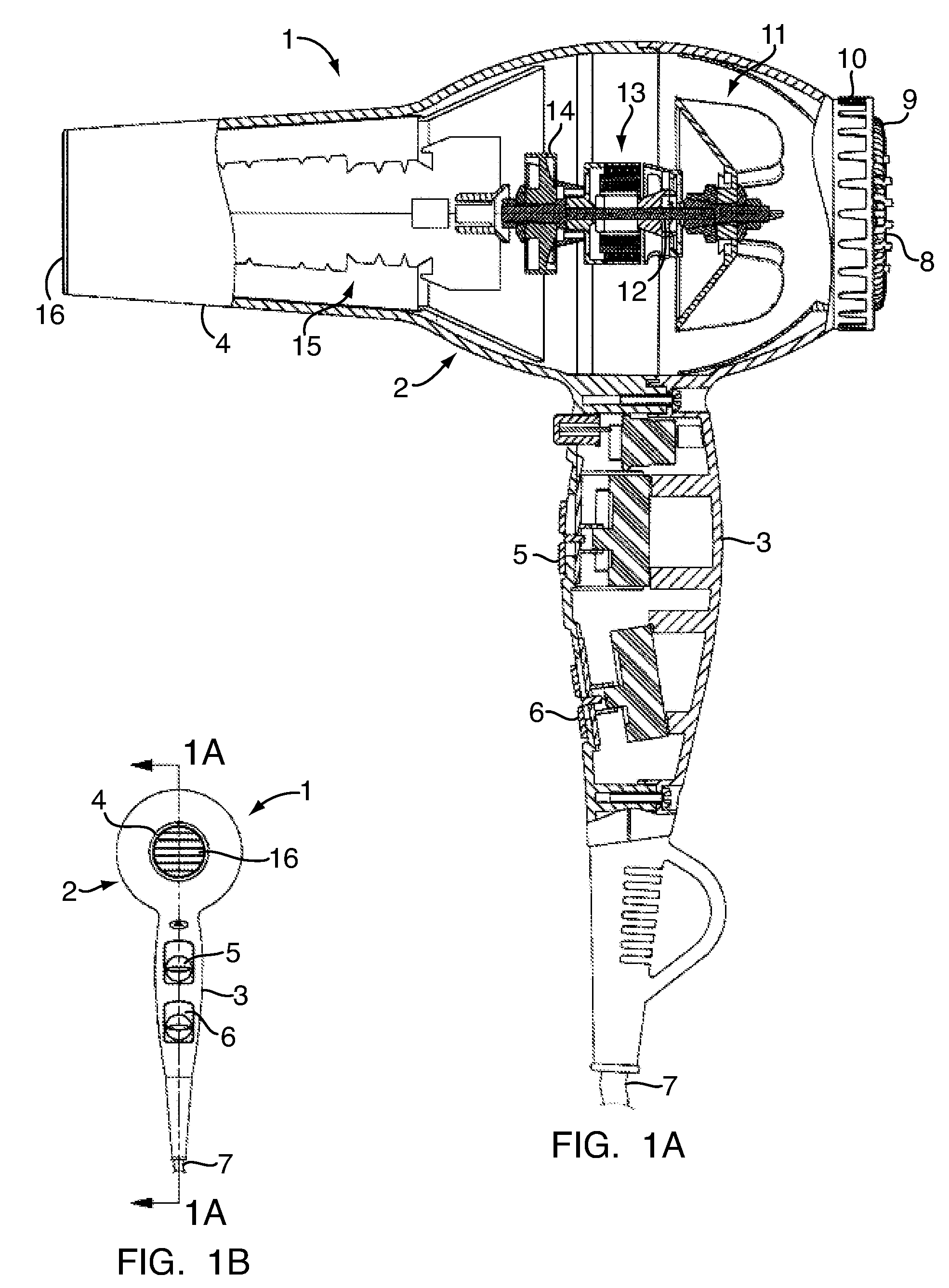
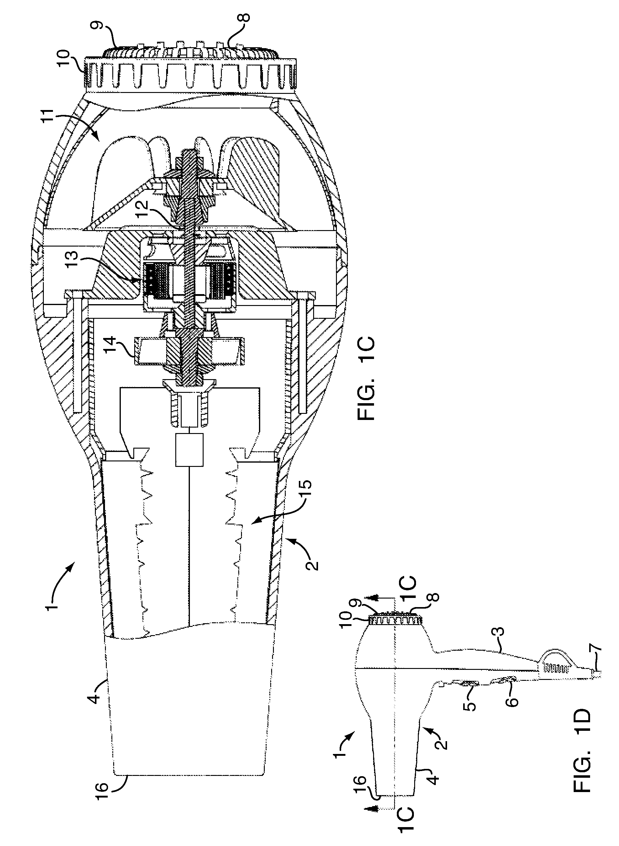
[0018]As shown in FIGS. 1A-1D, according to the present invention, a hair dryer 1 has a housing 2 comprising a handle section 3 and a nozzle section 4. The handle section 3 has one or more control buttons 5, 6 for controlling various operating functions of the hair dryer. A power cord 7 provides electricity from an external AC source, e.g., an electrical receptacle or outlet. Incoming airflow enters through an intake port 8, which can have a screen filter 9 secured by a retainer ring 10. Airflow is drawn in by a rotating fan blade assembly 11, which is connected to a rotating shaft 12 driven by a brushless electric motor 13. The incoming airflow passes the fan blade assembly 11 and some of it is re-circulated toward the motor 13 by a secondary fan 14 for cooling the motor 13, while the rest of the airflow is pushed past a heater assembly 15 and out the discharge end 16 of the nozzle section 4 as heated air.

[0019]With reference to FIGS. 2A-2F, the brushless electric motor 13 includes...

second embodiment

[0030]FIG. 8 shows an electronic control system 80. The control system 80 includes a TRIAC 82 and a bridge rectifier 84. The TRIAC 82 controls the bridge rectifier 84, which converts the input AC power to rectified DC. The rectified DC voltage is filtered by a capacitor 86. The bridge rectifier 84 is connected to the TRIAC 82 on one side and a dropper resistor 88 on the other side. The dropper resistor 88 drops the voltage to the DC supply. A zero cross reference, supplied by a voltage divider 90, provides an analog input to a zero cross detector built into the brushless motor controller board 92. The brushless motor controller 92 delays the triggering of the TRIAC 82 until the voltage of the AC input sine wave is at a safe operating voltage for the brushless control circuit 80 to start up. The time delay triggering is gradually decreased until a full waveform is energized by the TRIAC 82. This provides the correct DC voltage without the high voltage during start up typically seen w...


PUM


Abstract

A portable electric appliance (1, 23) such as a hand held hair dryer uses a brushless electric motor (13, 25) in combination with a secondary fan assembly (14) and/or an air scoop (24) to redirect air toward the motor (13, 25), to maintain a cool operating temperature. The appliance includes a control circuit (50, 80, 94, 102, 110) for controlling the brushless motor (13, 25) and other appliance features. The control circuit and the coil windings (21) of the brushless electric motor are designed to run the appliance at a relatively low current to accommodate a higher operating voltage, thereby operating at a low wattage for reducing extraneous or waste heat. This facilitates placement of the control circuit in a small, portable appliance, and may enhance operation of the appliance in certain modes such as a hair dryer “cool shot.”

Description

CROSS REFERENCE TO RELATED APPLICATIONS[0001]This application claims the benefit of U.S. Provisional Application Ser. No. 60 / 859,745, filed Nov. 17, 2006, hereby incorporated by reference herein in its entirety.FIELD OF THE INVENTION[0002]The present invention relates to portable electrical appliances including, but not limited to, hand held hair dryers, hair clippers, shavers, blenders, and food processors and, more particularly, to electrical appliances that use high speed rotational electric motors.BACKGROUND OF THE INVENTION[0003]Small appliances such as hair dryers, clippers, shavers, blenders, food processors, and others that require rotational electric motors use standard electric motors with brush-contact stator and rotor arrangements. Such motors have been in existence for a long time and are reliable, inexpensive, and durable. While they are generally suitable for what is regarded as ordinary performance, there is room for improvement in terms of rotational velocity, torqu...

Claims


Application Information

Patent Timeline
Patent Type & Authority Applications(United States)
IPC IPC(8): H02K7/14H02P7/285H02K11/04H02K9/06
CPCA45D20/10H02K7/145A45D20/12
Inventor CARLUCCI, VITO JAMES
Owner CONAIR CORP
Why Eureka
Try Eureka