Projection exposure apparatus, projection exposure method and projection objective

a technology of projection exposure and projection objective, which is applied in the direction of photomechanical treatment, printing, instruments, etc., can solve the problems of difficult to correct chromatic aberrations using purely refractive means in this wavelength range, and few sufficient transparent materials available for producing transparent optical elements, etc., and achieves narrow quality tolerances and production economics.

Active Publication Date: 2008-05-22
CARL ZEISS SMT GMBH
View PDF20 Cites 33 Cited by
  • Summary
  • Abstract
  • Description
  • Claims
  • Application Information

AI Technical Summary

Benefits of technology

[0012]It is an object of the invention to provide a projection exposure apparatus which is able to ensure, with relatively broadband projection radiation at operating wavelengths ofλ...

Problems solved by technology

At wavelengths λ≦200 nm, however, there are only a few sufficiently transparent materials available for producing the transparent optical elements.
However, since t...

Method used


Image

  • Projection exposure apparatus, projection exposure method and projection objective
  • Projection exposure apparatus, projection exposure method and projection objective
  • Projection exposure apparatus, projection exposure method and projection objective

Examples


Embodiment Construction

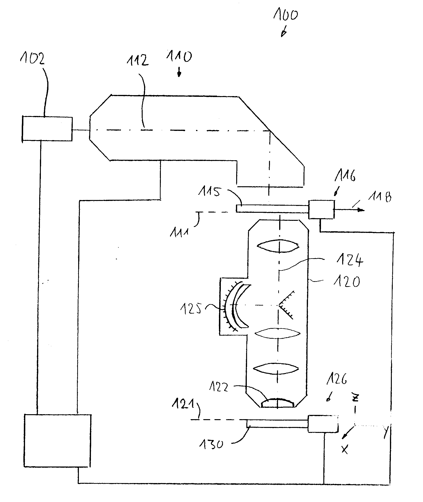
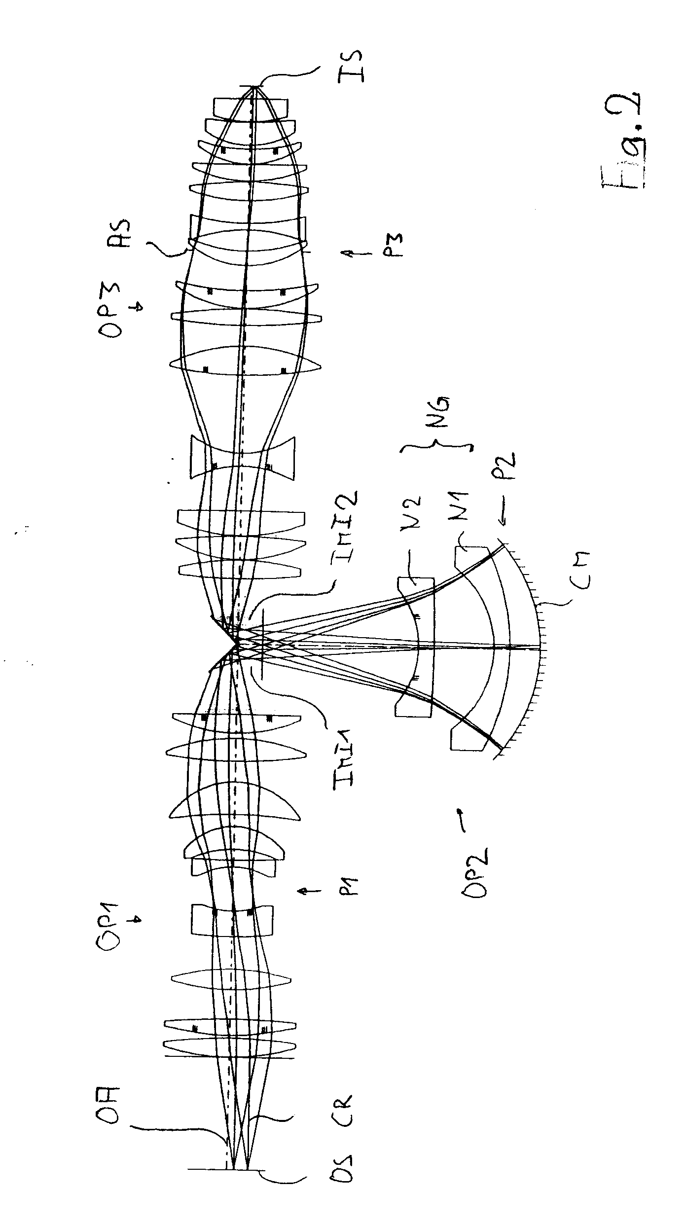
[0035]In the following description of preferred embodiments, the term “optical axis” denotes a straight line or a sequence of straight line segments through the centers of curvature of the optical components. The optical axis is folded at folding mirrors (deflection mirrors) or other reflective surfaces. In the examples, the object is a mask (reticle) having the pattern of an integrated circuit; a different pattern, for example of a grating, may also be involved. In the examples, the image is projected onto a wafer which is provided with a photoresist layer and which serves as a substrate. Other substrates, for example elements for liquid crystal displays or substrates for optical gratings, are also possible.

[0036]The specifications of the exemplary embodiments shown in the figures of the drawings are specified in tables, the numbering of which respectively corresponds to the numbering of the corresponding figure of the drawings.

[0037]FIG. 1 schematically shows a microlithography pr...


PUM


Abstract

A projection exposure apparatus for the exposure of a radiation-sensitive substrate arranged in the region of an image surface of a projection objective with at least one image of a pattern of a mask that is arranged in the region of an object surface of the projection objective has a light source for emitting ultraviolet light from a wavelength band having a bandwidth Δλ>10 pm around a central operating wavelength λ>200 nm; an illumination system for receiving the light from the light source and for directing illumination radiation onto the pattern of the mask; and a projection objective for the imaging of the structure of the mask onto a light-sensitive substrate. The projection objective is a catadioptric projection objective having at least one concave mirror arranged in a region of a pupil surface of the projection objective, and a negative group having at least one negative lens arranged in direct proximity to the concave mirror in a region near the pupil surface, where a marginal ray height (MRH) of the imaging is greater than a chief ray height (CRH).

Description

BACKGROUND OF THE INVENTION[0001]This application claims the benefit of German Patent Application No. DE 10 2006 022 958.4 filed on May 11, 2006. The disclosure of this patent application is incorporated herein in its entirety by reference.FIELD OF THE INVENTION[0002]The invention relates to a projection exposure apparatus for the exposure of a radiation-sensitive substrate arranged in the region of an image surface of a projection objective with at least one image of a pattern of a mask that is arranged in the region of an object surface of the projection objective and to a projection exposure method that can be carried out with the aid of the projection exposure apparatus and to a projection objective capable of being used in that apparatus and method.DESCRIPTION OF THE RELATED PRIOR ART[0003]Nowadays, predominantly microlithographic projection exposure methods are used for the fabrication of semiconductor components and other finely patterned components. This involves using masks...

Claims


Application Information

Patent Timeline
IPC IPC(8): G03B27/54G02B17/08
CPCG02B17/0892G03F7/70275G03F7/70225G02B27/18G03F7/20
Inventor ROSTALSKI, HANS-JUERGENFELDMANN, HEIKOULRICH, WILHELM
Owner CARL ZEISS SMT GMBH
Why Eureka
Try Eureka