
Method for filling holes with metal chalcogenide material

a technology of metal chalcogenide and filling holes, which is applied in the field of filling holes with metal chalcogenide materials, can solve the problems of inflexibility of material optimization, inability to meet the requirements of power budget, and inability to achieve the effect of reducing complexity, reducing cost and improving throughpu

Inactive Publication Date: 2008-05-29
GLOBALFOUNDRIES INC
View PDF6 Cites 61 Cited by
  • Summary
  • Abstract
  • Description
  • Claims
  • Application Information

AI Technical Summary

Benefits of technology

[0063]For thin-film deposition, the above-described solution was further diluted by mixing 1 mL of the above described precursor solution with 2 mL of anhydrous hydrazine. Films could then be spin coated from this diluted hydrazine-based precursor solution onto A-type substrates (described above for the In2Te3 example) using the same spin-coating process to that described above for In2Te3. In contrast to the In2Te3 example; however, the KSb5S8 films did not adequately wet the substrate surface during film formation, thereby resulting in film discontinuity across the surface (although material did deposit in the holes). To improve surface wetting and adhesion, an In2Te3 layer was first deposited on the substrate and then the KSb5S8 layer was placed on top. As seen in FIG. 5, the KSb5S8 deposits effectively in the holes. The darker bottom layer is the indium telluride, while the lighter material on top is the KSb5S8. Two iterations of the indium telluride coating process and two iterations of the KSb5S8 process were employed. There is still some roughness to the film outside the holes, which may be attributed to partial dissolution of the film during the various iterations of film deposition (2 depositions of In2Te3 and 2 interations of KSb5S8). Improved surface treatments (adhesion layers and / or processes to affect the wetting of the precursor solution) or use of a different solvent during spin coating should help to reduce this effect and improve the resulting film morphology.

Problems solved by technology

However, challenges regarding the power budget remain, and a practical cell requires decreasing the size of the switching volume.
The challenge thus is to provide a design that reduces the physical volume of that part of the memory cell that contains the active switching, while maintaining the desired properties of the material and contacts.
Sputtering requires expensive tools and targets and does not provide flexibility for material optimization.

Method used


Image

  • Method for filling holes with metal chalcogenide material
  • Method for filling holes with metal chalcogenide material
  • Method for filling holes with metal chalcogenide material

Examples


example 1

In2Te3

[0054]The solution used for spin-coating is prepared by stirring at room temperature (in an inert atmosphere) 0.5 mmol of elemental indium (57.4 mg) and 0.75 mmol of tellurium (95.7 mg) in 3 mL of distilled hydrazine. After stirring for approximately 1 week, only a small amount of the indium remains undissolved and an orange-yellow solution is formed. The solution is filtered to remove the remaining metal and is then ready for spin coating.

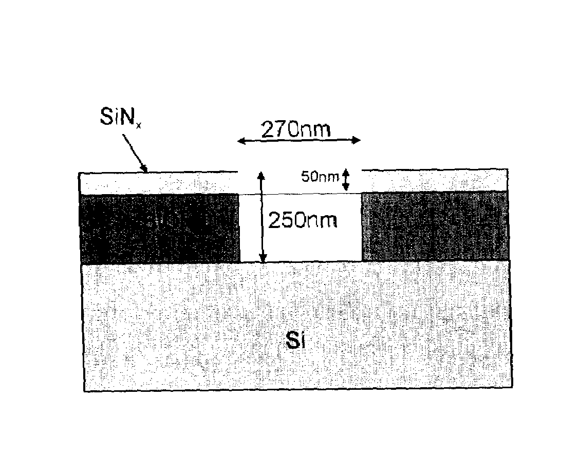
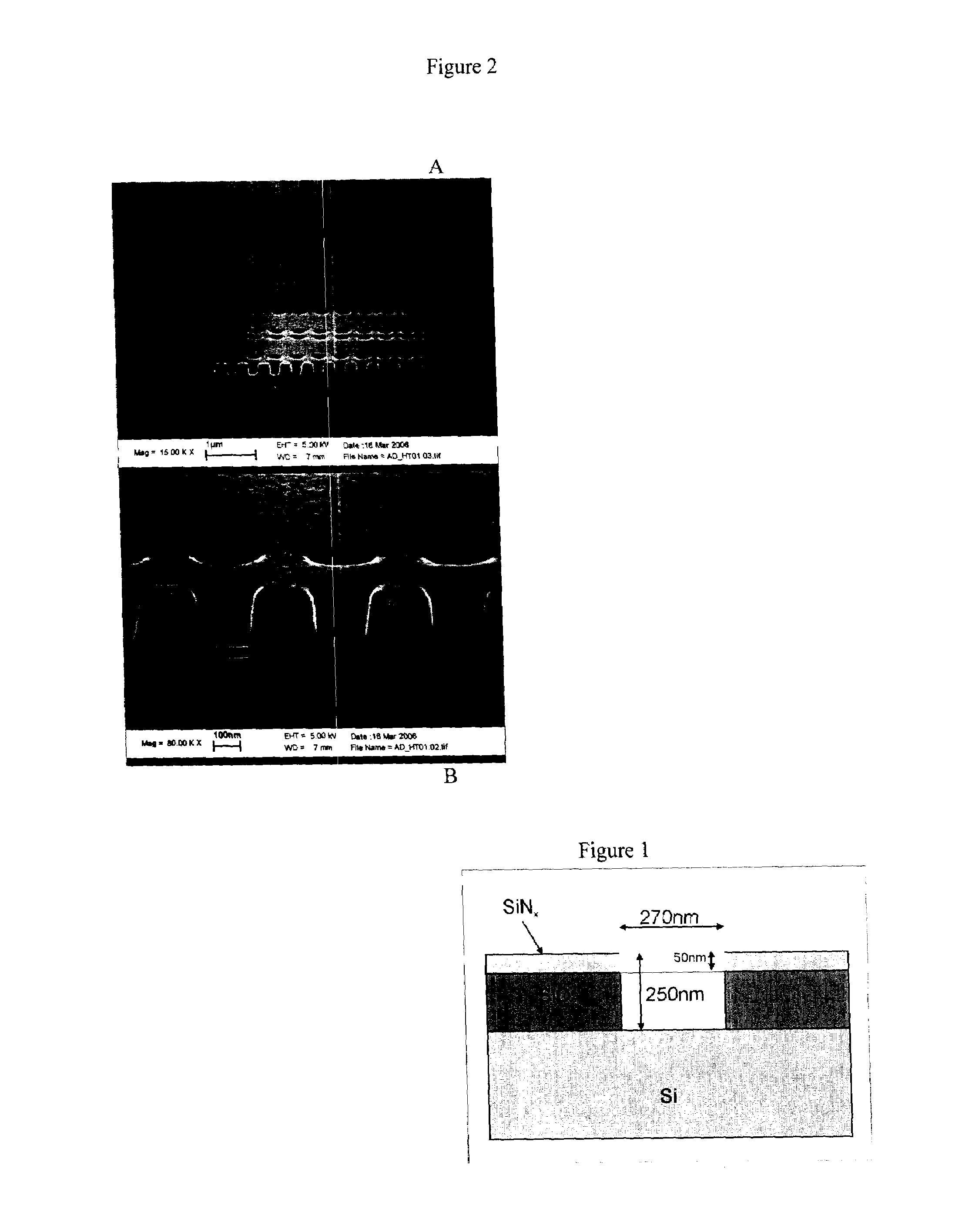
[0055]Two types of substrates are employed to test surface feature filling. In substrate A, the surface of the substrate is covered with holes that have an approximately 1:1 aspect ratio as shown in FIG. 1. In substrate B, the surface is covered with similar holes and channels, but rather provides a more abrupt aspect ratio of approximately 3.5:1. In each case, the substrates are cleaned by sonicating alternately in ethanol, dichloromethane and ethanol and are finally subjected to a 15 minute dip in a solution consisting of approximately a ...

example 2

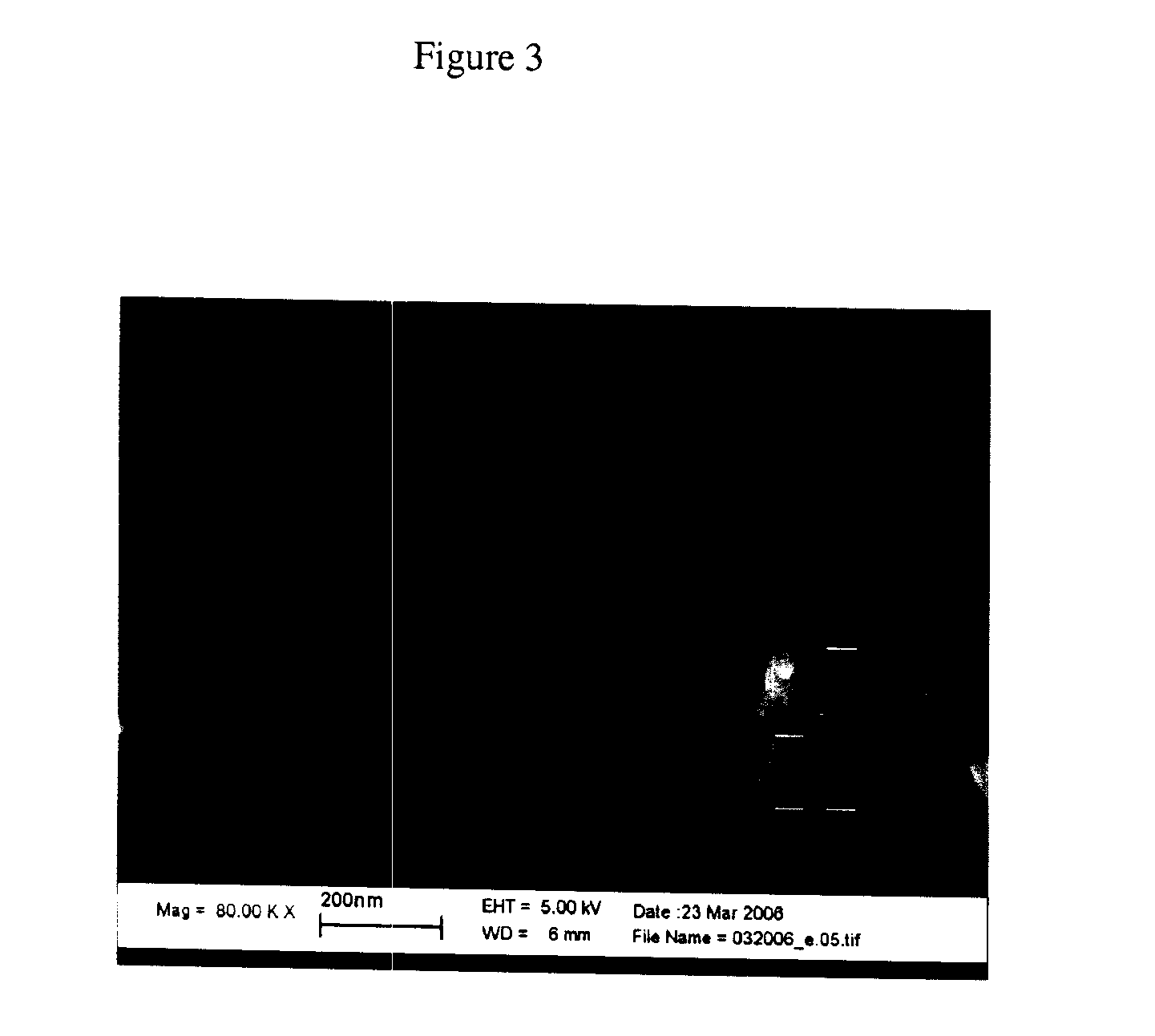
[0059]To demonstrate thicker coatings, it was necessary to apply several coatings of the indium telluride film. In FIG. 3, a substrate with three iterations of the film coating process described above is shown. Note the more complete hole filling by the indium telluride material. Attempts to produce thick films by using a much more concentrated solution or by using a slower spin speed (or by drop casting instead of spin coating) generally yielded films that exhibited a substantial amount of porosity, as a result of the need to remove gaseous products during the decomposition process. Therefore, the multiple deposition process is preferable for achieving a thick coating.

example 3

[0060]To illustrate the filling of larger aspect ratio features using the hydrazine-based solution approach, type B substrates (with approximately 3.5:1 aspect ratio features) were similarly processed and yielded the results shown in FIG. 4. Note that the holes and channels are adequately filled by the spin-coating process.


PUM


Abstract

A metal chalcogenide material is deposited into holes within a substrate surface. The method comprises obtaining a hydrophilic substrate surface; obtaining a solution of a hydrazine-based precursor of a metal chalcogenide; applying the solution onto the substrate to fill the holes with said precursor; and thereafter annealing the precursor to convert said precursor to said metal chalcogenide thereby producing holes in the substrate surface filled with a metal chalcogenide material.

Description

TECHNICAL FIELD[0001]The present disclosure relates to a method for filling holes with metal chalcogenide material. The present disclosure is especially advantageous for filling nano and micro scale holes or vias in a surface of a substrate.BACKGROUND[0002]Interest in using phase change materials (PCM) for microelectronic non-volatile memory devices has existed for several decades. The reason for this interest is based on the properties of these materials (generally metal chalcogenide alloys), which exhibit a ratio of resistivities in the amorphous over the crystalline phase of several orders of magnitude. More recently, progress in lithographic and deposition techniques have provided new momentum towards the realization of practical Phase Change Memory devices.[0003]However, challenges regarding the power budget remain, and a practical cell requires decreasing the size of the switching volume. The challenge thus is to provide a design that reduces the physical volume of that part o...

Claims


Application Information

Patent Timeline
IPC IPC(8): H01L45/00G03F7/00
CPCH01L45/06H01L45/142H01L45/1683H01L45/144H01L45/1608H01L45/143H10N70/231H10N70/8822H10N70/8825H10N70/8828H10N70/021H10N70/066
Inventor RUIZ, RICARDOMILLIRON, DELIA J.RAOUX, SIMONEMITZI, DAVID B.SCHROTT, ALEJANDRO G.
Owner GLOBALFOUNDRIES INC
Learn More