
High-efficiency, high-reliability fiber amplifier using engineered passband of photonic bandgap optical fiber

a fiber amplifier and passband technology, applied in the field of optical fiber amplifiers, can solve the problems of less reliable operation, high pump power is more expensive to obtain, and a significant portion of the edfa pump energy typically generated by the pump laser is wasted in amplifying noise, etc., to achieve the effect of improving the optical conversion and improving the efficiency of the amplifier

Inactive Publication Date: 2008-06-05
NORTHROP GRUMAN CORP
View PDF6 Cites 10 Cited by
  • Summary
  • Abstract
  • Description
  • Claims
  • Application Information

AI Technical Summary

Benefits of technology

[0013]Therefore, the amplified spontaneous emission outside the narrow passband will escape the fiber without being amplified such that the energy of the pump can be better utilized for amplifying the signal. The optical conversion efficiency of the amplifier is thus improved with a relatively low cost, small size, high power efficiency and reliability gains. The above-described concept can be applied to multiple passbands centered at different wavelengths, all within the gain spectrum.

Problems solved by technology

The disadvantage of such approach is that a significant portion of EDFA pump energy that is typically generated by a pump laser is wasted in amplifying the noise instead of being applied to amplify the desired signal.
Higher pump powers are more expensive to obtain and / or are less reliable to operate.

Method used


Image

  • High-efficiency, high-reliability fiber amplifier using engineered passband of photonic bandgap optical fiber
  • High-efficiency, high-reliability fiber amplifier using engineered passband of photonic bandgap optical fiber
  • High-efficiency, high-reliability fiber amplifier using engineered passband of photonic bandgap optical fiber

Examples


Embodiment Construction

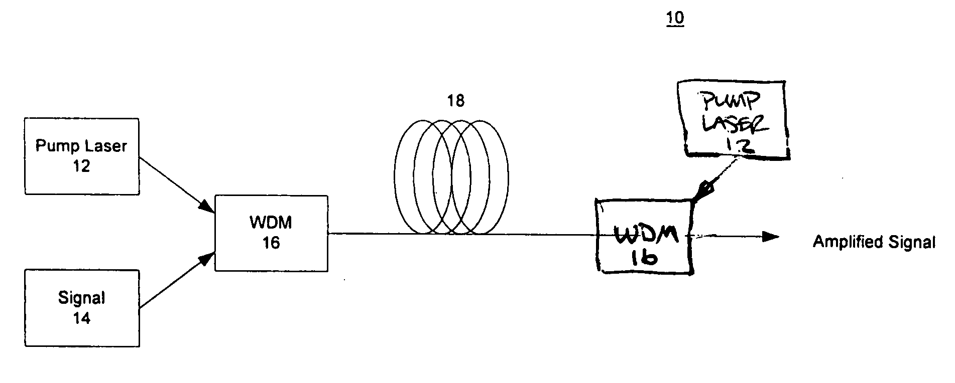
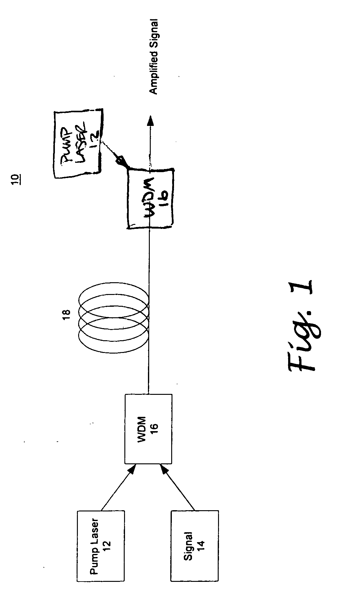
[0019]FIG. 1 provides a schematic illustration of a photonic crystal fiber amplifier 10. As shown, the photonic crystal fiber amplifier 10 includes at least one pump energy source 12, at least one coupler 16, and a length of optical fiber 18. Preferably, the pump energy source 12 includes a pump laser operative to generate a pump beam at a specific wavelength. A signal source 14 is adapted to generate a signal. The coupler 16 includes a wavelength division multiplexer or a conventional optical coupler operative to simultaneously couple the pump beam energy with the signal 14 for transmission from either end of the optical fiber 18. For example, FIG. 1 illustrates that the photonic crystal amplifier 10 can also be provided in a dual-pump 12 version. The photonic optical fiber 18 is doped with a gain medium such as erbium, ytterbium, thulium or other rare earth ions.

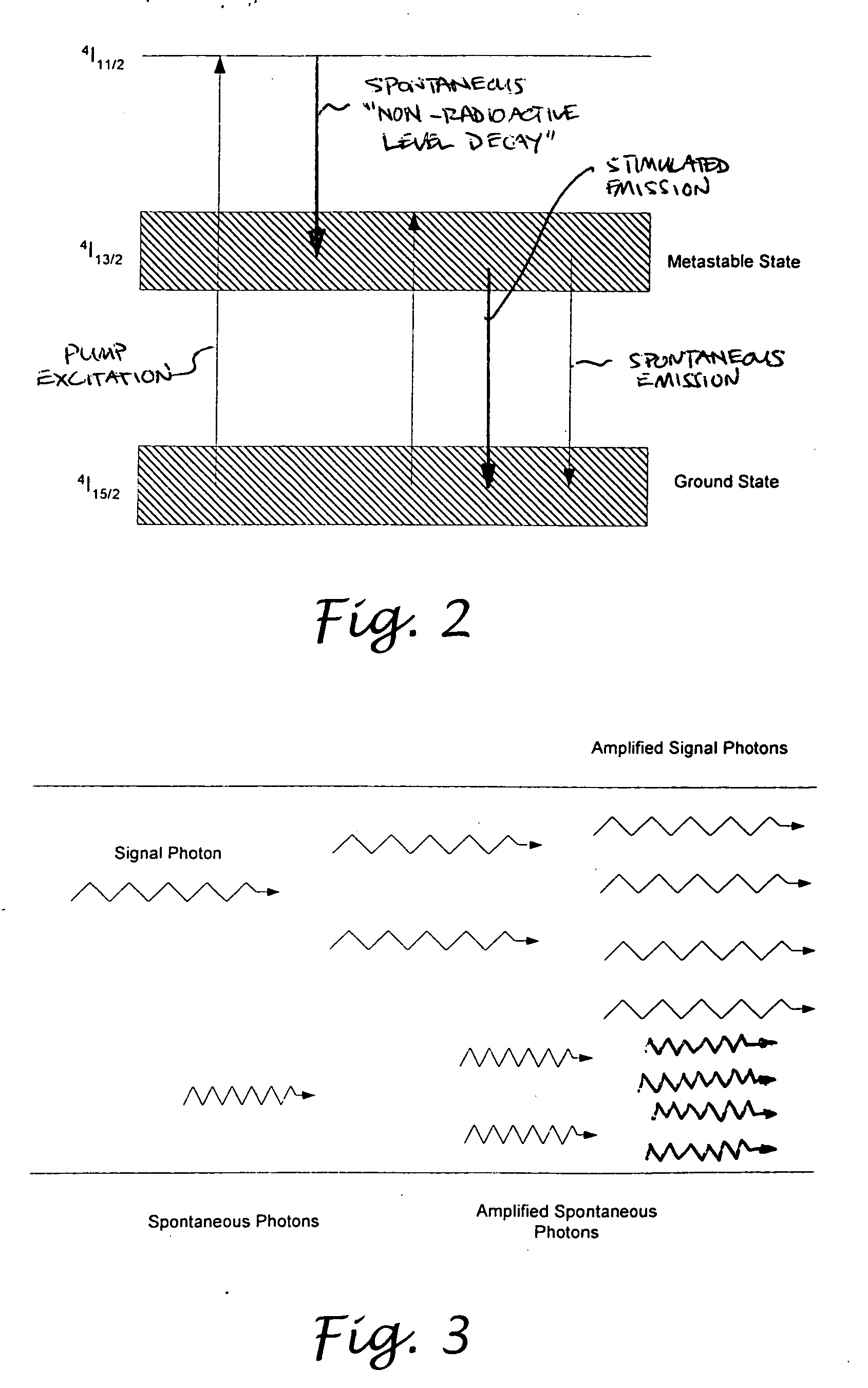
[0020]FIG. 2 illustrates the energy-level transition in erbium. As shown, there are three energy levels in the amplifica...


PUM


Abstract

A fiber amplifier is configured such that its spontaneous emissions are filtered out at the instant of creation. The fiber optic amplifier combines the gain medium of the fiber optical amplifier with a continuous filter to filter out the spontaneous emissions to prevent spontaneously emitted photons from stealing gain from signal photons. The photonic crystal fiber has a central core doped with a gain medium such as erbium, ytterbium or thulium ions. The central core of the photonic crystal fiber is surrounded by a cladding region having an array of holes or air voids that may be filled with materials with refractive index different from that of the central core. The array of holes are configured to restrict the wavelength range within which light can propagate inside the central core thereby providing continuous filtering functionality. The fiber amplifier has a pump operative to generate pump energy that is coupled to the photonic crystal fiber simultaneously with the signal. The wavelength of the pump energy is within the absorption band of the gain medium to facilitate amplification of the signal.

Description

CROSS-REFERENCE TO RELATED APPLICATIONS[0001]Not ApplicableSTATEMENT RE: FEDERALLY SPONSORED RESEARCH / DEVELOPMENT[0002]Not ApplicableBACKGROUND[0003]The present invention relates in generally to an optical fiber amplifier, and more particularly, to a high-efficiency, high-reliability fiber amplifier using an engineered passband of photonic bandgap optical fiber.[0004]A typical fiber amplifier configuration is disclosed in the document entitled “Erbium-Doped Fiber Amplifiers: Fundamentals and Technology” by P. C. Becker et al., the entire contents being incorporated by reference herein. In conventional optical fibers, total internal reflection is responsible for the guiding of light therein. Based on the principle of total internal reflection (TIR), an optical fiber typically consists of a central core surrounded by a cladding layer whose index of refraction n2 is slightly lower than that n1 of the core. The optical fiber is characterized by a normalized frequency as a function of th...

Claims


Application Information

Patent Timeline
IPC IPC(8): H01S3/09H01S3/00
CPCH01S3/06754H01S3/06708
Inventor BABICH, COOPER DOMINIC
Owner NORTHROP GRUMAN CORP
Learn More