Method for Application of a Thermal Barrier Coating and Resultant Structure Thereof

a technology of thermal barrier coating and resultant structure, which is applied in the direction of vacuum evaporation coating, coating, sustainable transportation, etc., can solve the problem of cooling air reducing the performance of the engin

Inactive Publication Date: 2008-06-05
UNIV OF VIRGINIA ALUMNI PATENTS FOUND
View PDF10 Cites 27 Cited by
  • Summary
  • Abstract
  • Description
  • Claims
  • Application Information

AI Technical Summary

Benefits of technology

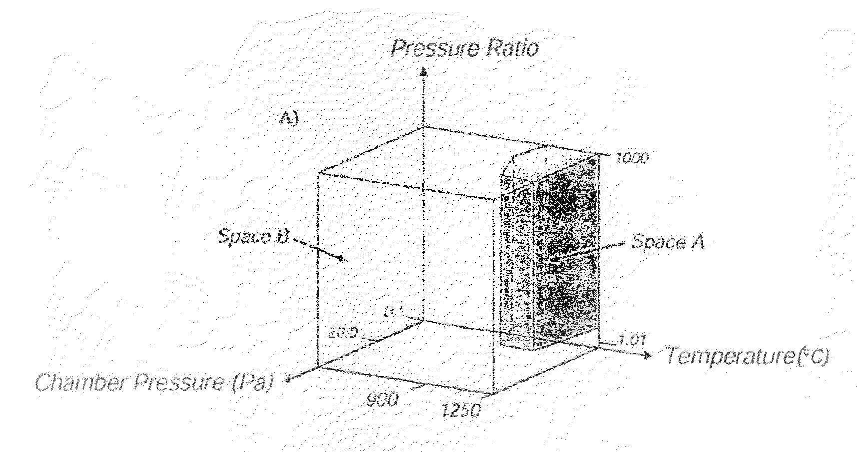
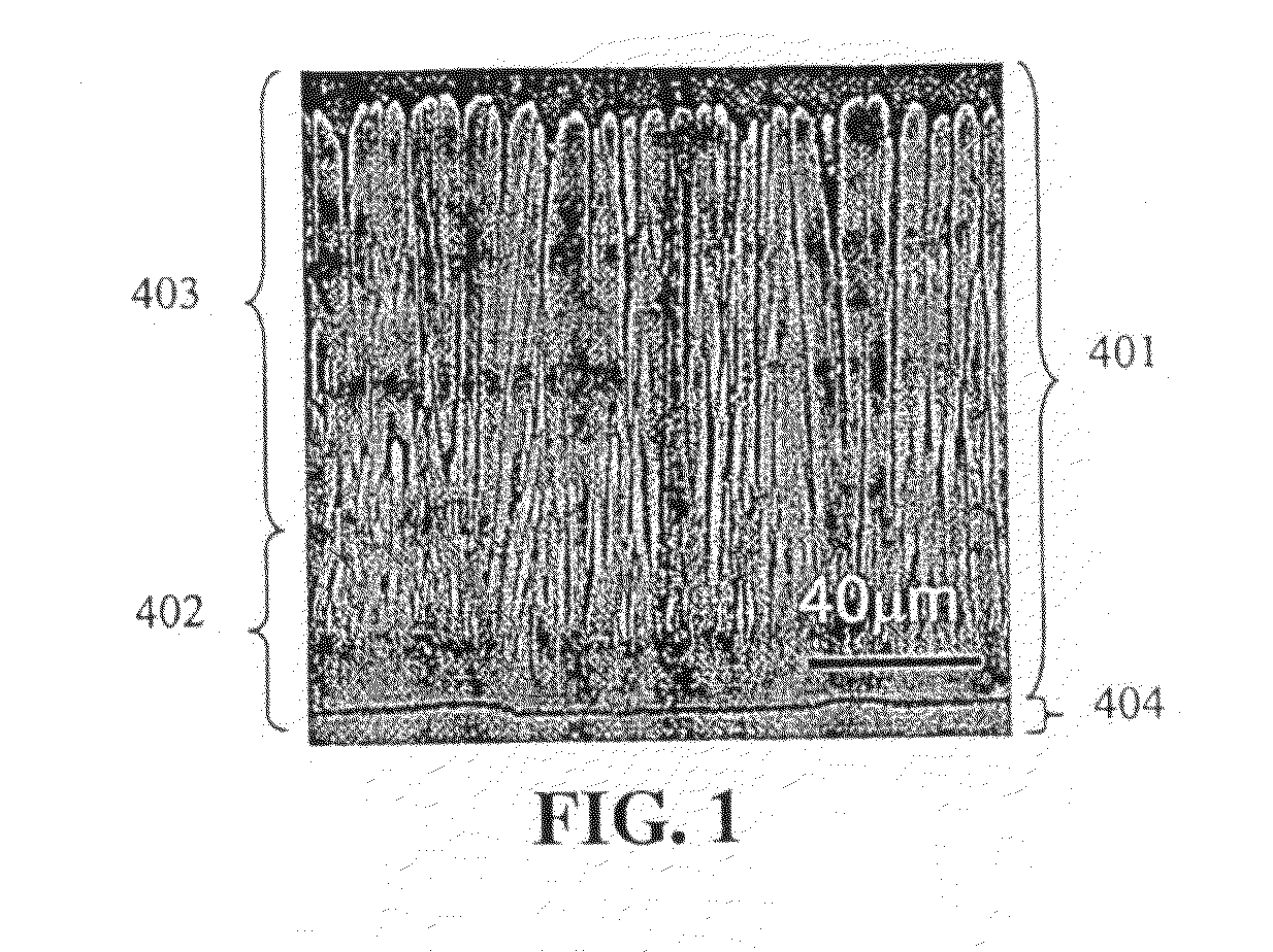
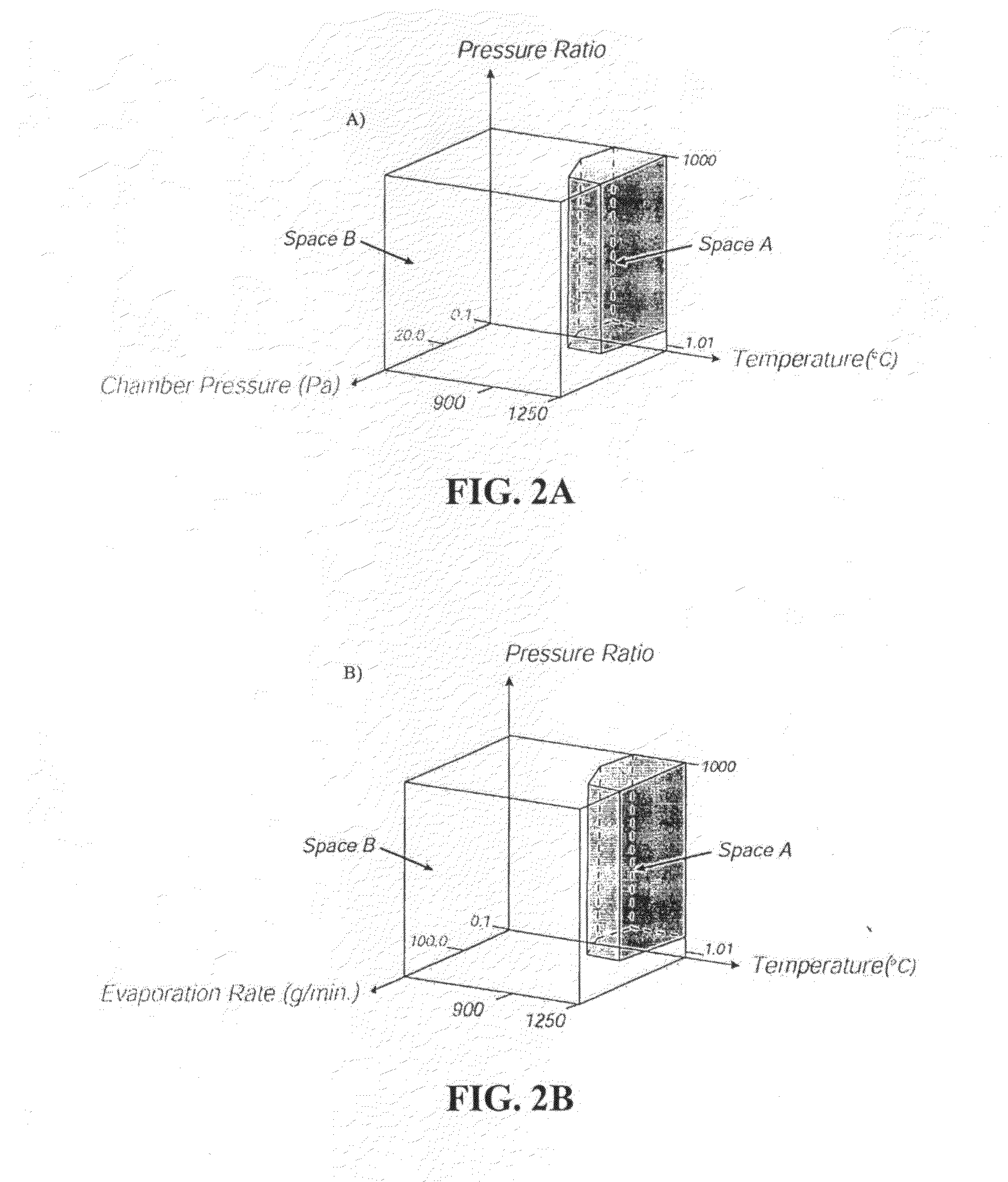
[0007]Embodiments of the present invention provides a process and apparatus, and resulting structure, for depositing ceramic coatings with preferred coating density, morphology and adherence for applications such as thermal protection of internally cooled components. Such components are found, but not limited thereto, in the hot sections of gas turbine and diesel engines and in turbo machinery. These coatings require a low thermal conductivity in the through thickness of the coating, high in-plane elastic compliance, high erosion and foreign object damage resistance and resistance to hot corrosion. These performance characteristics are determined by the coatings composition, the coatings morphology and the manner in which the coating is applied. Today's coatings are applied by either an air plasma spray or electron beam evaporation process that operates under high vacuum. This latter process results in a process recipe that creates a preferred morphology of the coating. Embodiments of the present invention utilizes, among other things, a high pressure, directed vapor deposition process in which evaporation is achieved by electron beam heating, laser ablation / evaporation, resistance heating or other mechanisms of evaporation. Because embodiments of the present invention process are different to the conventional EB-physical vapor deposition process used currently, it results in a different process for creating a preferred coating(s).

Problems solved by technology

By insulating the metallic component, its temperature is reduced allowing it to last longer or to survive with less cooling air (cooling air reduces the performance of the engine).

Method used


Image

  • Method for Application of a Thermal Barrier Coating and Resultant Structure Thereof
  • Method for Application of a Thermal Barrier Coating and Resultant Structure Thereof
  • Method for Application of a Thermal Barrier Coating and Resultant Structure Thereof

Examples


Embodiment Construction

[0025]Vapor phase processes are widely used for applying thermal and environmental protection coating systems to components. They are widely used to protect the hot structural components of many gas turbine engines that must operate at temperatures approaching their melting point, See S. M. Meier and D. K. Gupta, Trans. of the ASME, 116, 250 (1994), of which is hereby incorporated by reference herein in its entirety. As gas inlet temperatures continue to rise, failure by thermally-induced mechanisms has been avoided by making airfoil components with internal cooling conduits, and injecting compressor discharge air to decrease the component temperature, See A. J. Glassman, Turbine Design and Application, Vol. 3, NASA-SP-290-VOL-3, NASA Lewis Research Center (1975), of which is hereby incorporated by reference herein in its entirety. To maximize engine efficiency, however, it is desirable to minimize the use of this air for cooling purposes. Traditionally, this has been accomplished b...


PUM

PropertyMeasurementUnit
pressureaaaaaaaaaa
temperatureaaaaaaaaaa
pressureaaaaaaaaaa

Abstract

Provided herein are methods and apparatuses, and resulting structures, for depositing ceramic coatings with preferred coating density, morphology and adherence for applications such as thermal protection of internally cooled components. Such components are found in, but not limited thereto, the hot sections of gas turbine and diesel engines and in turbo machinery. These coatings require a low thermal conductivity in the through thickness of the coating, high in-plane elastic compliance, high erosion and foreign object damage resistance and resistance to hot corrosion. The methods and apparatuses discussed herein provide, among other things, how to manipulate the process conditions in EB-DVD systems to deposit high quality, highly efficient TBS top coats as well as how to deposit high quality TBC top coats onto positions that are in the line-of-sight, as well as non-line of sight, of the vapor source.

Description

CROSS-REFERENCE TO RELATED APPLICATIONS[0001]The present invention claims priority under 35 U.S.C. Section 119(e) of the earlier filing date of U.S. Provisional Application Ser. No. 60 / 490,969, filed Jul. 29, 2003, entitled “Method for Application of a Thermal Barrier Coating and Resultant Structure thereof,” the entire disclosure of which is hereby incorporated by reference herein.[0002]The present application is also related to U.S. application Ser. No. 10 / 476,309, filed Oct. 29, 2003, entitled “Method and Apparatus for Efficient Application of Substrate Coating,” of which is assigned to the present assignee and is hereby incorporated by reference herein in its entirety.GOVERNMENT SUPPORT[0003]This invention was made with government support under Grant Nos. N001014-98-1-0355; N00014-00-1-0147; and N00014-97-97-0106. The government has certain rights in the invention.BACKGROUND OF THE INVENTION[0004]Thermal Barrier Coatings are used extensively in aircraft and industrial gas turbin...

Claims


Application Information

Patent Timeline
Patent Type & Authority Applications(United States)
IPC IPC(8): C23C4/04C23C16/22C23C16/06C04BC23C14/08C23C14/28C23C14/30C23C14/32
CPCY02T50/67C23C14/30Y02T50/60
Inventor HASS, DEREK D.WADLEY, HAYDN N.G.
Owner UNIV OF VIRGINIA ALUMNI PATENTS FOUND
Why Eureka
Try Eureka