Precision abrasive machining of work piece surfaces

a technology for workpiece surfaces and abrasives, applied in the field of machine control, can solve the problems of total film thickness tolerance, film thickness variability of approximately 15 nm, and pressure of the bonnet against the surface, and achieve the effect of reducing spot size variations and producing surface height fluctuations

Inactive Publication Date: 2008-06-05
CORNING INC
View PDF15 Cites 2 Cited by
  • Summary
  • Abstract
  • Description
  • Claims
  • Application Information

AI Technical Summary

Benefits of technology

[0012]In accordance with the present invention, the relative spacing between a bonnet / pad type tool and the surface of the work piece is controlled dynamically so that the area of the abrasive pad in contact with the surface of the work piece (also referred to herein as “spot size”) remains constant, thereby eliminating spot size variations and the accompanying variations in material removal, which produce surface height fluctuations. Spot size variation results from various sources including radial error motion of the pad. For a given internal pressure of the tool, the spot size will vary in relationship to the actual axial position between the tool and the work piece surface. In accordance with a first embodiment of the invention, the force between the tool and the surface of the work piece is sensed and the axial spacing between the tool and the surface of the work piece is controlled in reverse sense to the force variation, in order to compensate for changes in spot size. In accordance with this first embodiment, dynamic real time control is exercised, for example, by using a server control subsystem.

Problems solved by technology

This is normally an interference spacing that would place the front of the bonnet past the surface of the work piece, causing compression of the bonnet against the surface.
It has been found that a radial error motion of approximately 50 microns may result in a film thickness variability of approximately 15 nm, larger than the total film thickness tolerance.
However, this radial error motion can rarely be reduced below 30 microns.

Method used


Image

  • Precision abrasive machining of work piece surfaces
  • Precision abrasive machining of work piece surfaces
  • Precision abrasive machining of work piece surfaces

Examples


first embodiment

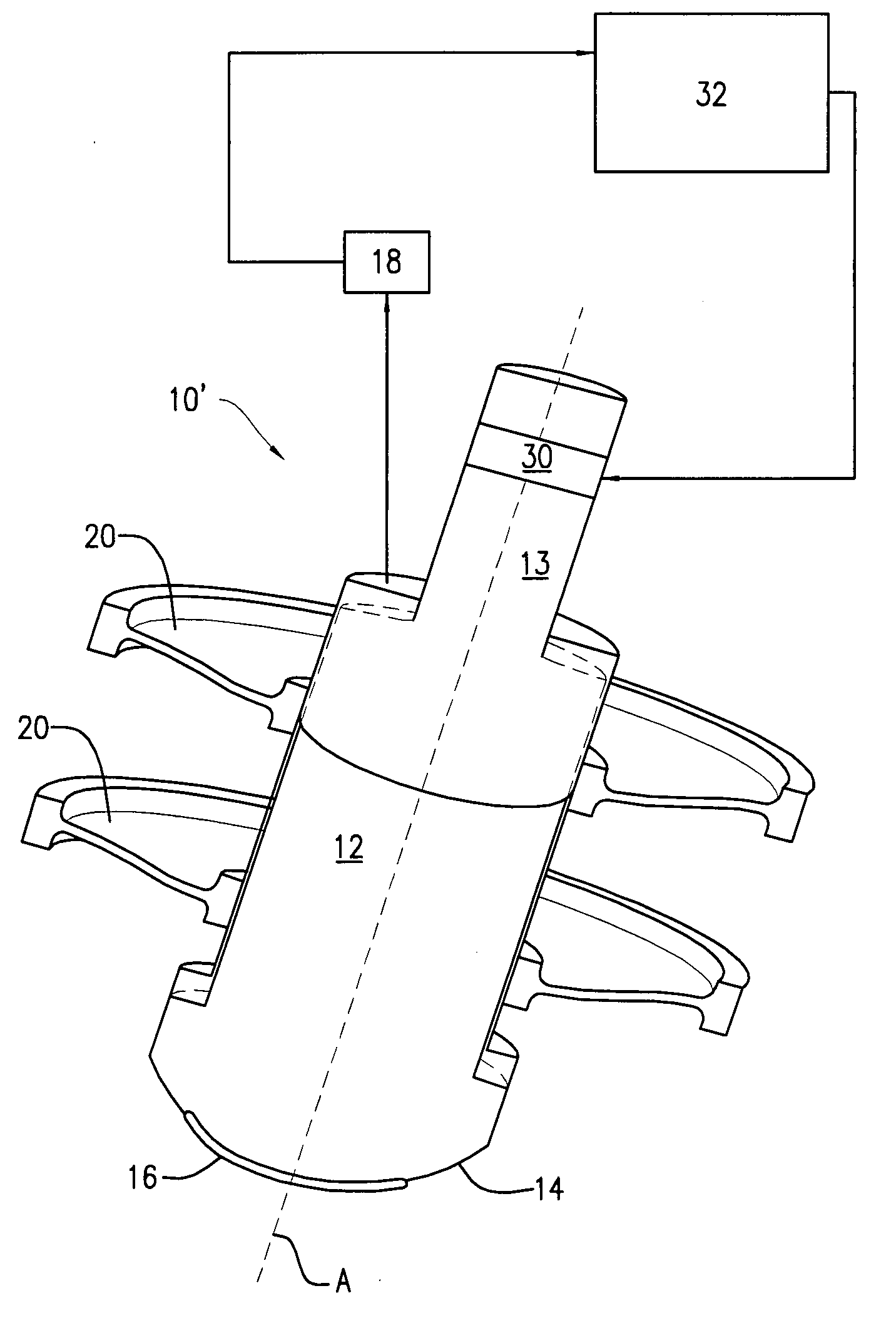
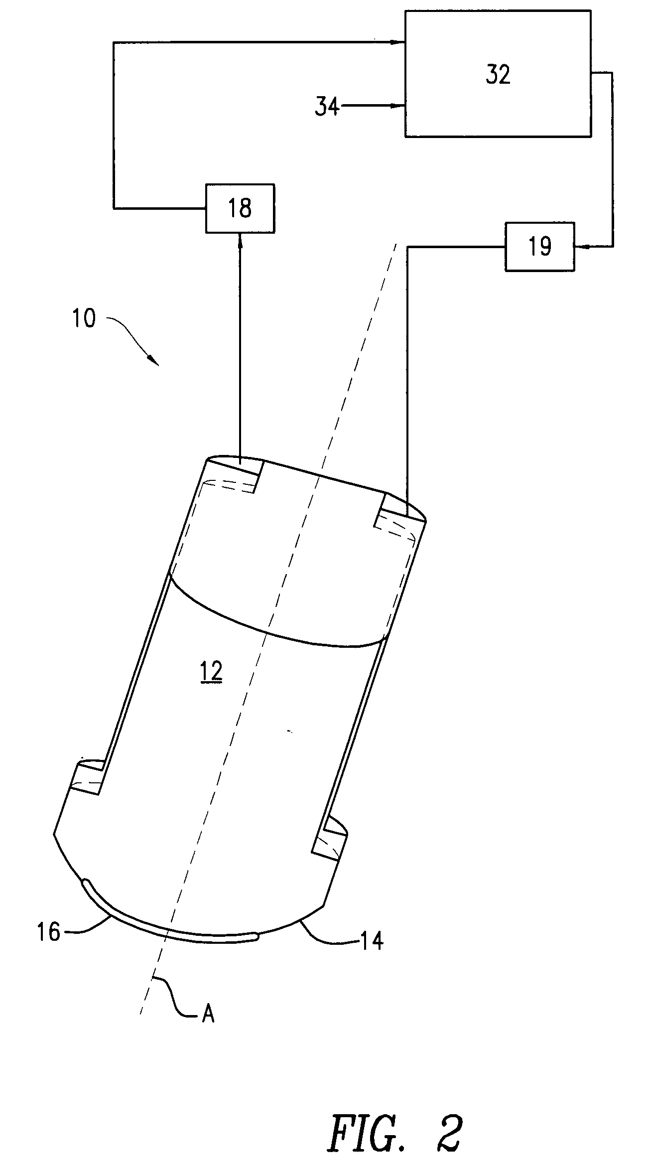
[0023]FIG. 2 is a schematic / block diagram illustrating a first embodiment in accordance with the present invention. Specifically, there is disclosed a tool 10 as in FIG. 1 in combination with a control subsystem 32, which controls the spacing between tool 10 and the surface of a work piece in relationship to the force between them.

[0024]The work piece may be a silicon-on-insulator (SOI) structure, such as silicon-on-glass (SOG). As used herein, “silicon-on-insulator” or “silicon-on-glass” shall be construed more broadly as including semiconductor materials other than silicon or those including silicon, and it will be understood to embrace insulator materials other than glass. For example, other useful semiconductor materials for practicing the invention include, but are not limited to, silicon germanium (SiGe), silicon carbide (SiC), germanium (Ge), gallium arsenide (GaAs), GaP, and InP. Also for example, other insulator materials may be employed for practicing the invention, includ...

second embodiment

[0033]FIG. 5 is a flow chart illustrating the process of a second embodiment in accordance with the present invention. In this case, tool 10 or 10′ is operated to compensate for spot size variations without using a servo control system. Periodically (e.g., daily) positioning mechanism 19 is subjected to a learning operation. This involves an initial step of setting tool 10 to a reference rotational orientation and setting the force between tool 10 and the work piece so as to create the desired spot size. This step is depicted in block 50. The angular orientation of body 12 is then incremented by rotating the body about axis A by a predetermined amount (block 52). The tool to work piece spacing is then adjusted to remove any change that may have occurred in the force sense by sensor 18 (block 54) and the change in spacing is stored (block 56). By virtue of a test performed at block 58, the steps in block 52-56 are repeated until body 12 has completed a complete 360° rotation about ax...

third embodiment

[0034]FIG. 6 is a schematic diagram illustrating a third embodiment in accordance with the present invention. In this case, the work piece W is supported on a table T with the tool 10′ positioned over the surface S of the work piece W. In operation, tool 10 would be scanned with respect to the surface S. This could be achieved by translating the tool 10 making use of its positioning system 19 (see FIG. 19) and / or translating the table T. Below the table T, there are provided a plurality of distance sensor / actuator pairs P each including a sensor 60 and a linear actuator 62. In this embodiment, there are three such pairs P, and they are in a triangular arrangement. The tool 10 is used to orthogonalize the table in the usual manner. That is, with table T empty, the tool 10 is positioned over the surface S, for example, over the left most pair P, and using its positioning mechanism 19 the distance between tool 10 and surface S is adjusted until sensor 18 senses a predefined force. Ther...


PUM


Abstract

The spacing between an abrasive type surface polishing tool and the surface of the work piece that is being polished is controlled dynamically so that variations in the area of the abrasive pad in contact with the surface of the work piece compensated, thereby eliminating size variations in this contact area and the accompanying variations in material removal that produce surface height fluctuations.

Description

CROSS REFERENCE TO RELATED APPLICATIONS[0001]This application claims the benefit of priority under 35 U.S.C. § 119(e) of U.S. Provisional Application Ser. No. 60 / 872,009 filed on Nov. 30, 2006.BACKGROUND OF THE INVENTION[0002]The present invention relates generally to machine control and, more particularly, concerns a method and a system for precision machining or finishing of article surfaces. It finds application, among other uses, in polishing of the semiconductor layer of semiconductor-on-insulator structures.[0003]The present invention will be disclosed in terms of a particular application. However, other applications are disclosed and further applications will be apparent to those skilled in the art. Particular applications were disclosed for convenience of description and without the intention of limiting the invention to any of them.[0004]To date, the semiconductor material most commonly used in semiconductor-on-insulator structures has been silicon, and glass is a common in...

Claims


Application Information

Patent Timeline
Patent Type & Authority Applications(United States)
IPC IPC(8): B24B49/00
CPCB24B7/228B24B49/16B24B13/01B24B7/22
Inventor STOCKER, MARK ANDREW
Owner CORNING INC
Why Eureka
Try Eureka