Decomposition of waste products formed in slurry catalyst synthesis

Inactive Publication Date: 2008-06-12
CHEVROU USA INC
View PDF14 Cites 11 Cited by
  • Summary
  • Abstract
  • Description
  • Claims
  • Application Information

AI Technical Summary

Benefits of technology

[0010]The decomposition process also provides flexibility regarding where slurry hydroprocessing of heavy oils may be performed. Such processes often have metals recovery units following the hydroprocessing reactors. If the invention of this application is employed, th

Problems solved by technology

Decomposition generally does not provide all of the ammonia and H2

Method used


Image

  • Decomposition of waste products formed in slurry catalyst synthesis
  • Decomposition of waste products formed in slurry catalyst synthesis
  • Decomposition of waste products formed in slurry catalyst synthesis

Examples


Example

EXAMPLE

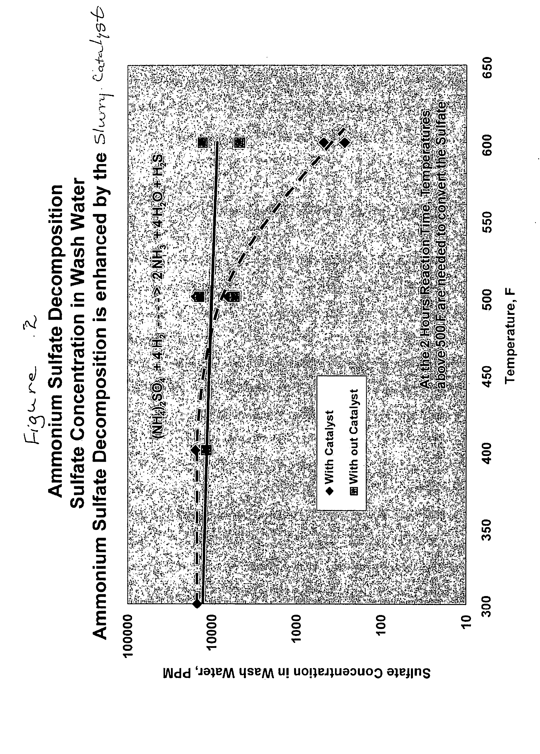
[0028]FIG. 2 is a graph of sulfate concentration in wash water v. temperature for two mixtures. One mixture is a solution of ammonium sulfate alone. The other mixture is an ammonium sulfate solution combined with a slurry catalyst comprising molybdenum and nickel, prepared in the catalyst synthesis unit. The ammonium sulfate admixed with the catalyst begins to decompose into hydrogen sulfide and ammonia at about 500 F., following a two hour residence time. This apparent from the dramatic decrease in the sulfate concentration in wash water at 500 F. There is no apparent decomposition in the solution containing only ammonium sulfate at the same conditions. FIG. 2 demonstrates the criticality of the presence of slurry catalyst as prepared in the catalyst synthesis unit.


PUM

PropertyMeasurementUnit
Temperatureaaaaaaaaaa

Abstract

This application discloses a process for decomposition of ammonium sulfates found in a stream comprising ammonium sulfate and slurry catalyst in oil. The ammonium sulfate is broken down into ammonia and hydrogen sulfide gas. These gases have many uses throughout the refinery, including the preparation of slurry hydroprocessing catalyst.

Description

FIELD OF THE INVENTION[0001]This application discloses a process for decomposition of ammonium sulfate.BACKGROUND OF THE INVENTION[0002]Slurry catalyst compositions, means for their preparation and their use in hydroprocessing of heavy feeds are known in the refining arts. Some examples are discussed below:[0003]U.S. Pat. No. 4,710,486 discloses a process for the preparation of a dispersed Group VIB metal sulfide hydrocarbon oil hydroprocessing catalyst. Process steps include reacting aqueous ammonia and a Group VIB metal compound, such as molybdenum oxide or tungsten oxide, to form a water soluble oxygen-containing compound such as ammonium molybdate or tungstate.[0004]U.S. Pat. No. 4,970,190 discloses a process for the preparation of a dispersed Group VIB metal sulfide catalyst for use in hydrocarbon oil hydroprocessing. This catalyst is promoted with a Group VIII metal. Process steps include dissolving a Group VIB metal compound, such as molybdenum oxide or tungsten oxide, with a...

Claims


Application Information

Patent Timeline
IPC IPC(8): B01J38/48
CPCB01J27/0515B01J27/30B01J38/68C01C1/24C01B17/164C22B23/026C22B34/345C01C1/028C22B7/009Y02P10/20Y02P20/52Y02P20/584B01J38/48
Inventor REYNOLDS, BRUCE E.BRAIT, AXEL
Owner CHEVROU USA INC
Why Eureka
Try Eureka