Ceramic-encased hot surface igniter system for jet engines

Inactive Publication Date: 2008-06-19
STATE OF FRANKLIN INNOVATIONS
View PDF23 Cites 32 Cited by
  • Summary
  • Abstract
  • Description
  • Claims
  • Application Information

AI Technical Summary

Benefits of technology

[0014]According to the present invention, an advanced ceramic-encased hot surface igniter system for jet engines is presented. The advanced ceramic-encased hot surface igniter system comprises at least one electrical resistance heated element encased in a durable, thermal and mechanical shock resistant, high temperature advanced ceramic compound such as silicon nitride. The one or more advanced ceramic-encased hot surface igniter elements are mounted within a combustion chamber of a jet engine enclosure or within the afterburner section of a jet propulsion engine's exhaust. In operation, a c

Problems solved by technology

However, the afterburner consumes large amounts of fuel.
Injection of water into the air-compressor inlet also increases the thrust, but can be used only at take-off because of the high water consumption.
Additionally, the metal surfaces can also suffer embrittlement.
Hence, these designs have not been widely employed in initiation of combustion for turbine engines.
When voltage is applied to the hot surface ignite

Method used


Image

  • Ceramic-encased hot surface igniter system for jet engines
  • Ceramic-encased hot surface igniter system for jet engines
  • Ceramic-encased hot surface igniter system for jet engines

Examples


Embodiment Construction

[0025]In the following detailed description of the embodiments, reference is made to the accompanying drawings that form a part hereof, and in which are shown by way of illustration, and not by way of limitation, specific embodiments in which the invention may be practiced. It is to be understood that other embodiments may be utilized and that logical, mechanical and electrical changes may be made without departing from the spirit and scope of the present invention.

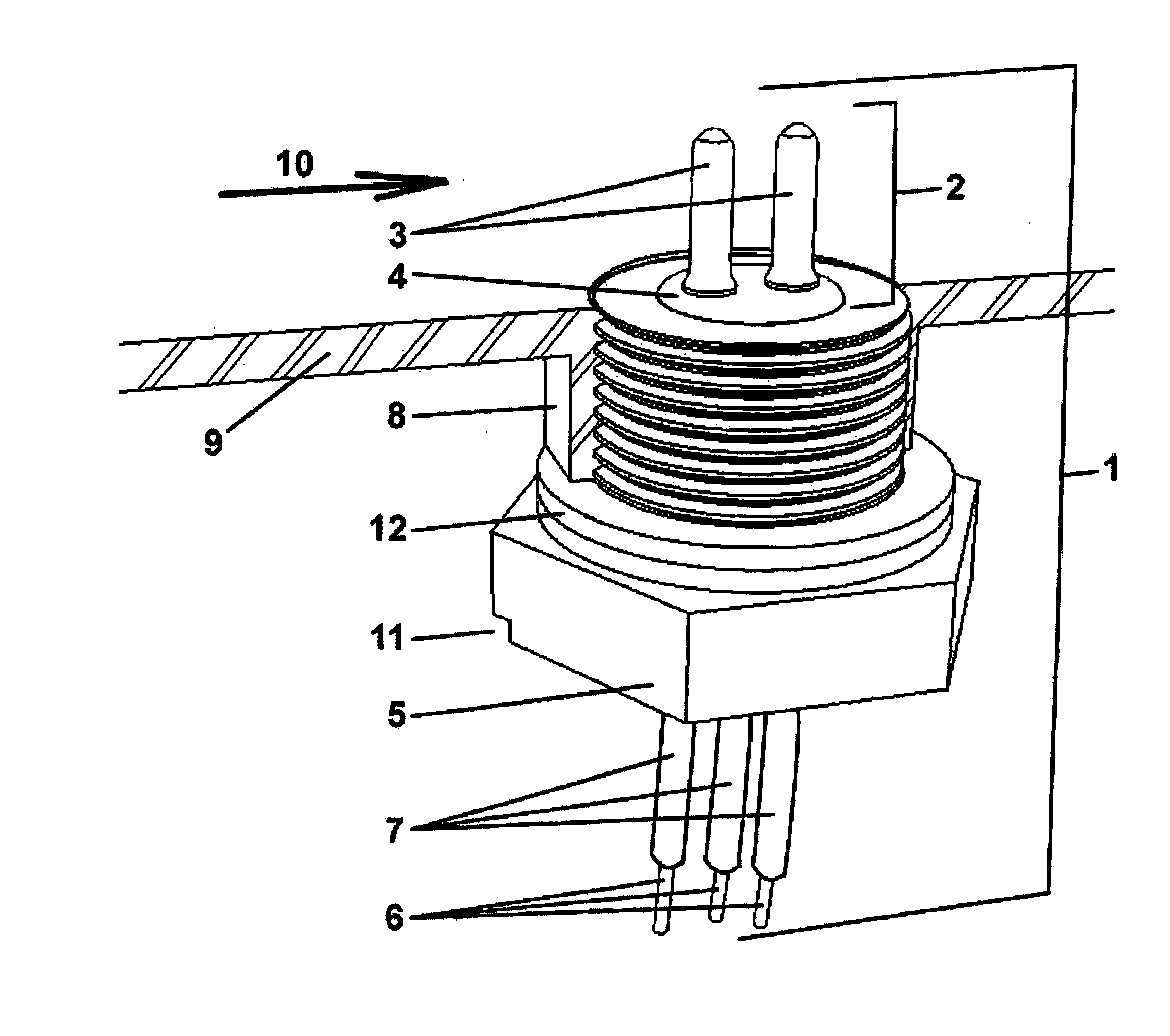
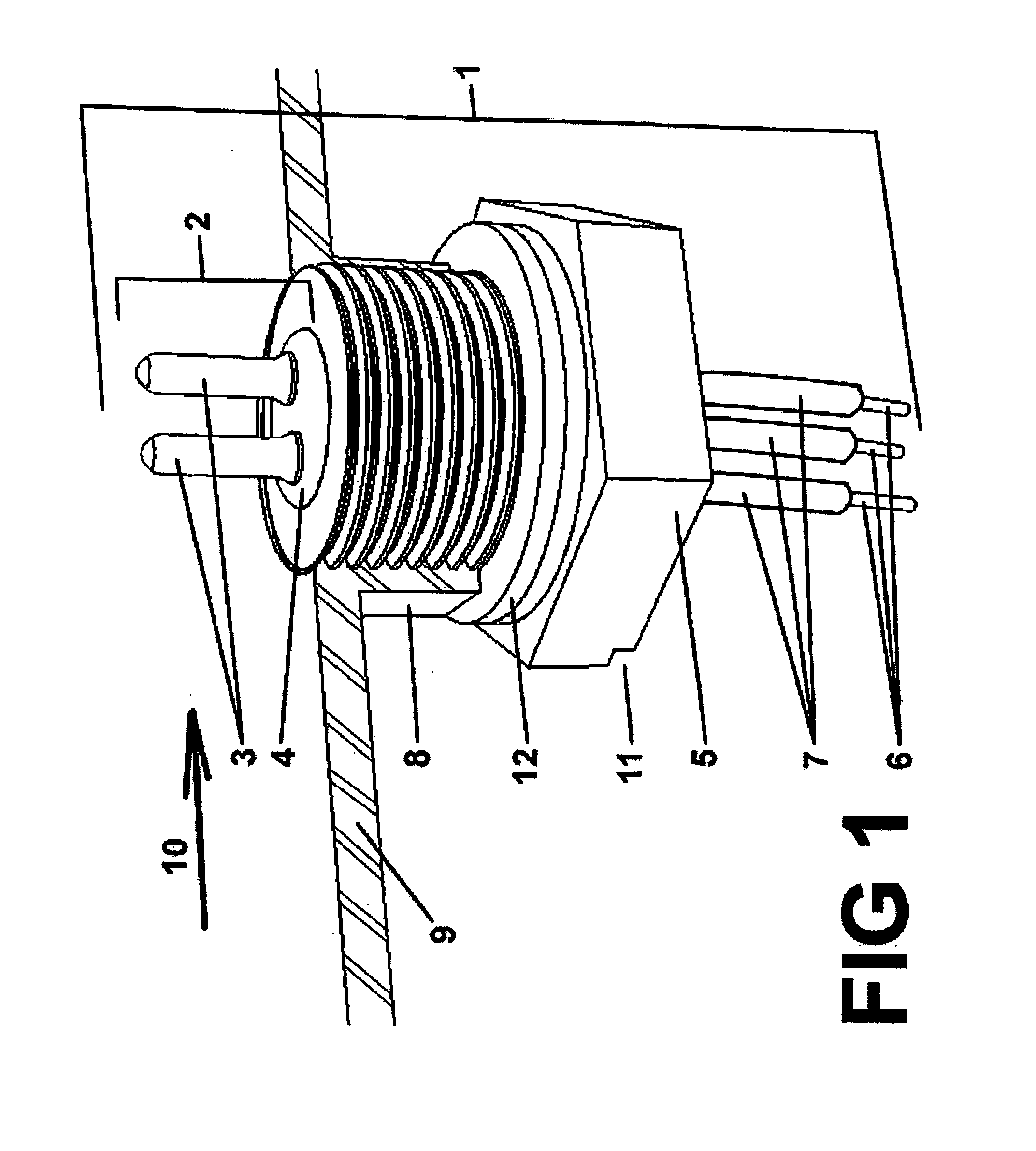
[0026]The hot surface igniter device described herein can be designed to be applicable to new, original equipment manufacturer (OEM) and existing (i.e., retrofit) jet propulsion or torque-producing engines such as, for example, gas turbine and rapid air movement (RAM) / supersonic combustion rapid air movement (SCRAM) jet engine installations (with or without afterburner capability) and replace the current “spark-gap” types of igniter. This design can offer significant advantages such as, for example, simplified design, rel...


PUM


Abstract

A ceramic-encased hot surface igniter system for jet engines is presented. The advanced ceramic-encased hot surface igniter system comprises at least one electrical resistance heated element encased in a durable, thermal and mechanical shock resistant, high temperature advanced ceramic compound such as silicon nitride. The one or more advanced ceramic-encased hot surface igniter elements are mounted proximally upstream or within a combustion chamber of a jet engine enclosure or within the afterburner section of a jet propulsion engine's exhaust. The surface temperature of each ignition element's encasement being of sufficient temperature to cause the ignition of a gaseous, atomized, or liquid fuel.

Description

CROSS-REFERENCE TO RELATED APPLICATIONS[0001]This application claims the benefit of U.S. Provisional Application Ser. No. 60 / 875,262, filed Dec. 15, 2006.BACKGROUND OF THE INVENTION[0002]The present invention, generally, relates to igniter system for a jet engine system and, in particular, relates to silicon nitride-encased hot surface igniter system for jet engine system.[0003]The four basic parts of a typical jet engine are the compression section, turbine, combustion section and propelling nozzles. In general, a jet engine can be comprised of the following working cycles: The compression cycle where work is done to increase pressure and decrease the volume of the air resulting in a corresponding rise in temperature. The combustion cycle when fuel is added to the air and ignited to increase the temperature causing a corresponding increase in volume while the pressure remains almost constant. The expansion cycle where there is a decrease in temperature and pressure with a correspon...

Claims


Application Information

Patent Timeline
IPC IPC(8): F02C7/264
CPCF02C7/266F02K3/10Y02T50/671F23D2207/00F23Q7/00F23D2206/10Y02T50/60
Inventor EASON, MARTIN P.HEMPHILL, WILLIAM K.OLSEN, MARTIN E.SIMS, J. PAUL
Owner STATE OF FRANKLIN INNOVATIONS
Why Eureka
Try Eureka