

Plasma ignition device
a technology of ignition device and plasma, which is applied in the direction of spark plugs, machines/engines, pulse generation by energy-accumulating elements, etc., can solve the problems of internal combustion engine misfire, and achieve the effect of suppressing the wear of the cathod
- Summary
- Abstract
- Description
- Claims
- Application Information
AI Technical Summary
Benefits of technology
Problems solved by technology
Method used
Image

Examples
first embodiment
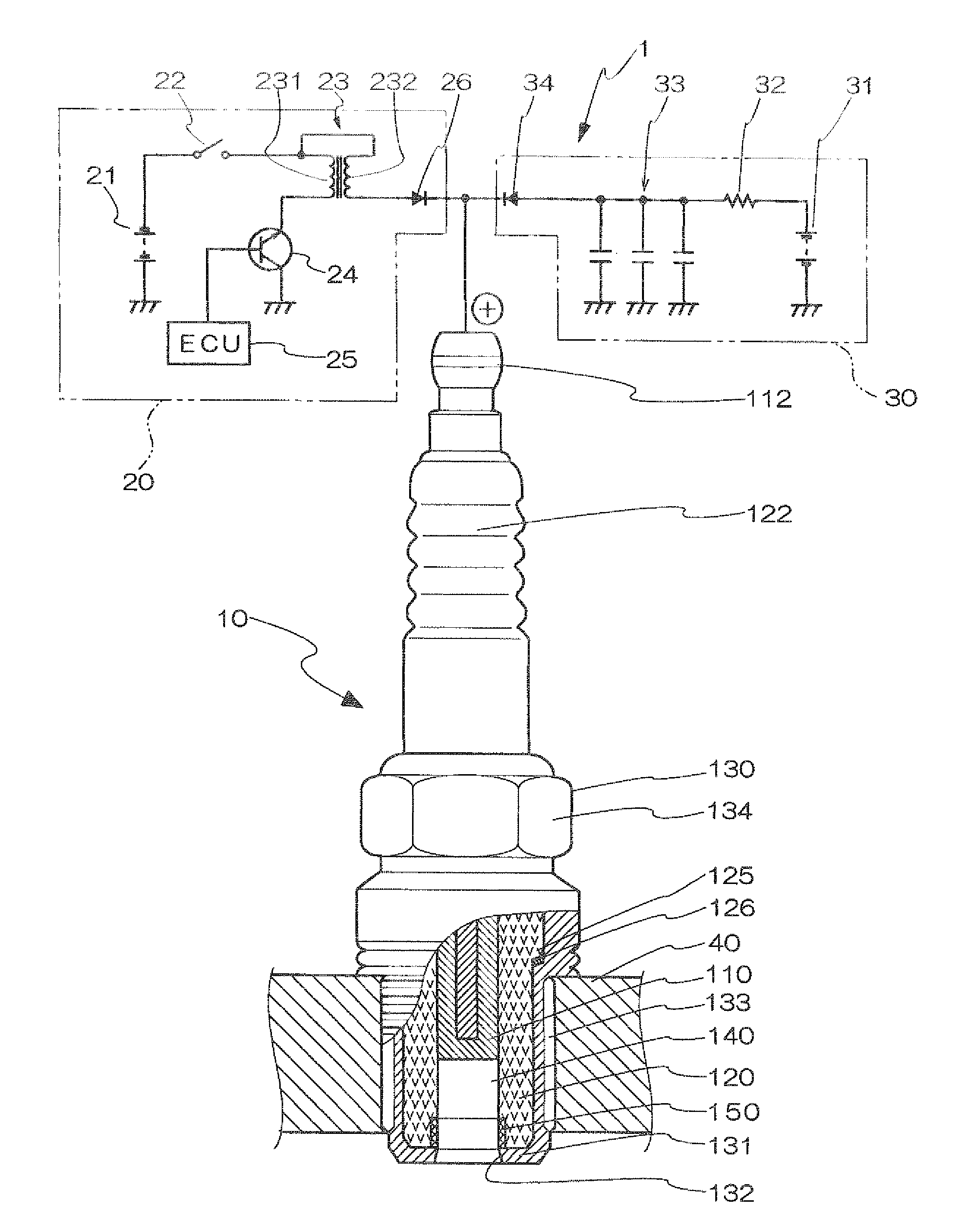
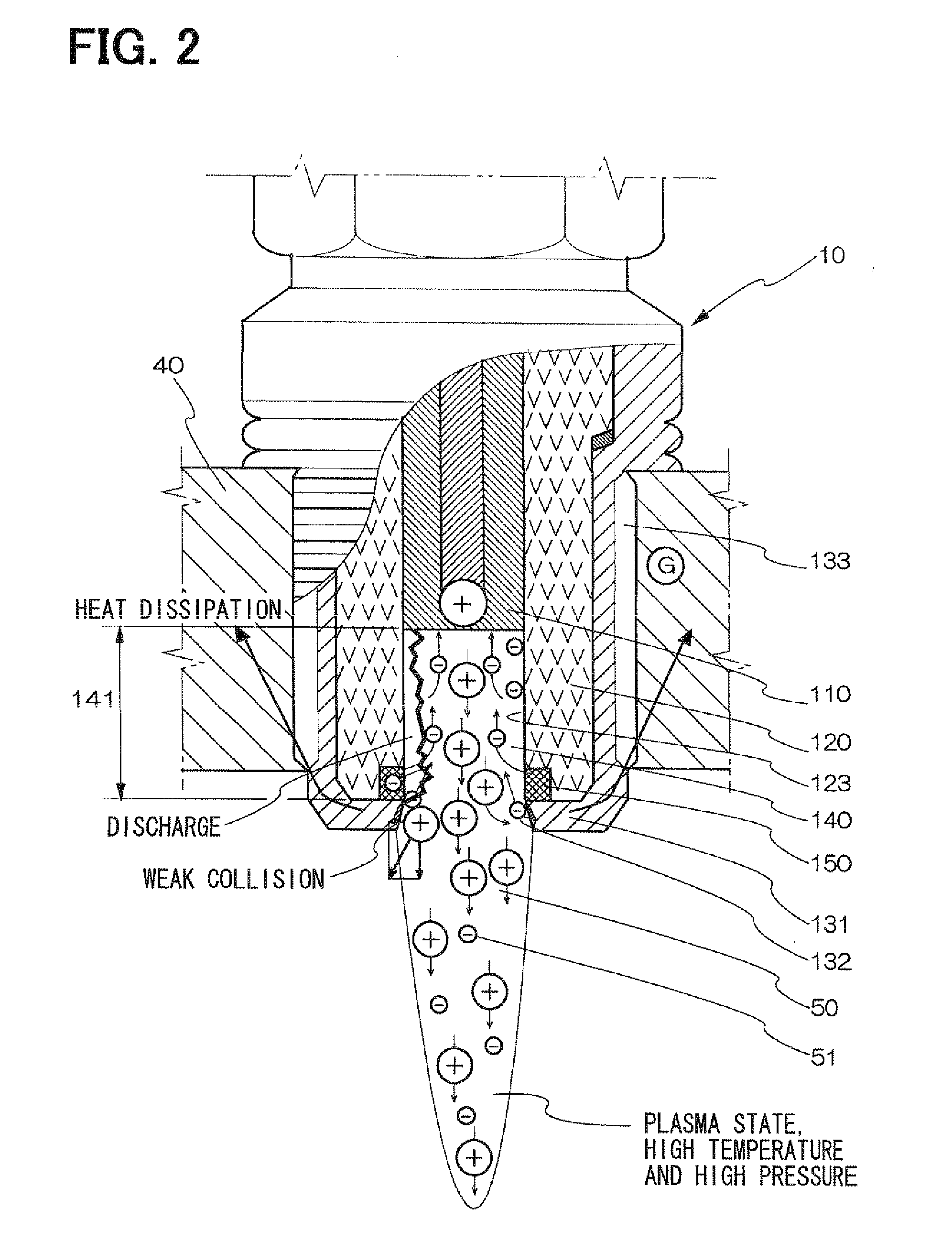
[0035]Referring first to FIG. 1, a plasma ignition device 1 is constructed with a plasma ignition plug 10, a discharging electric power supply circuit 20 for discharge, and a plasma generating electric power supply circuit 30 for generating plasma. Both of the electric power supply circuits 20 and 30 are high voltage electric power circuits.
[0036]The plasma ignition plug 10 includes a center electrode 110 having the shape of a rod, an electrical insulator 120 as a cylindrical insulation member to insulate and retain the center electrode 110, and a metallic housing 130 having the shape of a cylinder and a closed end to cover the electrical insulator 120.
[0037]The tip part (end) of the center electrode 110 is made of an electrically conductive material having a high melting point, a center electrode inner rod made of a metallic material having a high electrical conductivity and a high thermal conductivity, such as a steel material, is formed in the interior, and a center electrode ter...
second embodiment
[0056]In a second embodiment, as shown in FIG. 3A, a protection layer 160 is formed so as to cover the surface exposed in the engine block 40 other than the surface facing the discharge space 140 of the ground electrode opening 132.
[0057]Further, the diameter of the ground electrode opening 132 increases so as to be larger toward the tip and a protection layer opening 161 communicating with the ground electrode opening 132 is formed in the protection layer 160. The protection layer 160a is formed into a nearly annular shape with an insulating material separately from the ground electrode 131 and is joined with the ground electrode 131 by means of screw joining, fitting, or the like.
[0058]In the present embodiment, in addition to the advantages similar to those in the first embodiment, even when, by long time use, the erosion of the surface facing the discharge space of the ground electrode opening 132 progresses by the cathode sputtering and an eroded part 139 subsiding toward outsi...
third embodiment
[0060]In a third embodiment, as shown in FIG. 4A, the protection layer 160 is formed so that only a part of the side surface of the opening of the ground electrode 131 is exposed to the discharge space 140 as the ground electrode opening 132.
[0061]In addition to the advantages of the second embodiment, the electric field strength increases at the discharge portion and discharge is facilitated by reducing the surface area of the ground electrode opening 132. It is thus possible to further reduce the wear speed of the ground electrode 131.
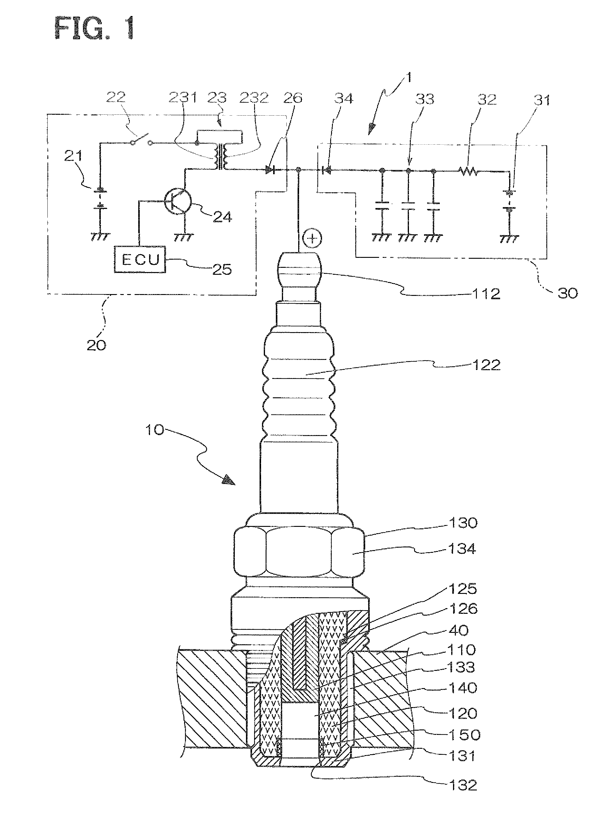
[0062]It is generally considered that, when channeling is formed on the inner wall of the electrical insulator 120 forming the discharge space 140, discharge of electrons into the discharge space 140 is hindered. However, it is expected that channeling formed on the bottom face of the electrical insulator 120 has the functions of suppressing the increase of a discharge potential and compensating the wear of the ground electrode 131.
[0063]Consequently...
PUM
 Abstract
Description
Claims
Application Information