Alignment and Attachment of a Heat Exchanger Cartridge to a Pump Device

a technology of heat exchanger and pump device, which is applied in the field of infusion device, can solve the problems of placing the patient at further risk, and affecting the normal operation of the pump, so as to prevent the crimping or obstructing of the tubing

Active Publication Date: 2008-06-19
SMISSON CARTLEDGE BIOMEDICAL
View PDF45 Cites 39 Cited by
  • Summary
  • Abstract
  • Description
  • Claims
  • Application Information

AI Technical Summary

Benefits of technology

[0018]In another example of the pump system provided for, the pump housing includes at least one sensing device and the cartridge includes at least one detector interface correspondingly aligned with the sensing device or devices and an infusion tubing exposed at the detector interface or interfaces. The sensing device is formed as a c-shaped clamp having substantially the same inner diameter as the outer diameter of the infusion tubing

Problems solved by technology

It is known that the injection of cold fluids into a patient's body can create a major source of conductive heat loss within the patient, often placing the patient at further risk by cooling, too quickly or, to a temperature where physiological damage can occur.
For instance, if blood reaches a certain temperature then hemolysis, the destruction or severe degradation, of the blood cells can occur.
Likewise, if the fluid is heated too high and then introduced into the patient's body, physiological damage resulting from exposure to excessive temperatures such as burns or other such scarring can occur.
Likewise, heating the fluid over a prolonged period of time can lead to increased exposure of the material to the environment creating risks of contamination.
Such systems are usually cumbersome, require frequent cleaning, and can pollute the clinical environment through the introduction of an additional substance—the heating liquid.
Such a system can be deleterious to a sterile environment and may not be properly transported.
Furthermore, these systems also have large mass, which require significant power to heat that mass yielding a significant time to achieve that temperature, or achieve a stasis when a cold mass (like a bag of chilled fluid) is introduced.
An additional problem to be avoided is the danger to the patient caused by current leakage in the system circuitry and specifically the circuitry used to achieve the warming characteristics that may be in close contact to the blood being infused to the patient.
Capacitive coupling, the transfer of energy from one element to another by means of mutual capacitance, could possibly cause enough current leakage to the heating system, and, potentially, to the patient and cause electric shock.
In such instances, traditional fluid heating systems often place the fluid at risk by exposure to temperatures which c

Method used


Image

  • Alignment and Attachment of a Heat Exchanger Cartridge to a Pump Device
  • Alignment and Attachment of a Heat Exchanger Cartridge to a Pump Device
  • Alignment and Attachment of a Heat Exchanger Cartridge to a Pump Device

Examples


example

Dialysis

[0156]In yet another embodiment, the pump device, described herein, may be used during renal replacement therapy, such as kidney dialysis, to treat patients with renal impairment or failure. Accordingly, this embodiment may be used to circulate cleansed or filtered blood through a patient.

[0157]A device configured for use in this embodiment may include at least two pumping mechanisms, at least two dynamic range motor drive assemblies, a central controller, and a dialysate bath. Accordingly, the blood may be pumped by one pumping mechanism and motor drive assembly through multiple capillary tubes, forming a semi-permeable membrane between the dialysate bath and the blood, as is known in the art. The dialysate may be pumped by another pumping mechanism and motor drive assembly across the capillary tubes in a direction opposite of the direction the blood is pumped through the capillary tubes, so as to create a counter current bath of osmotic fluid. The osmotic fluid or dialysat...


PUM


Abstract

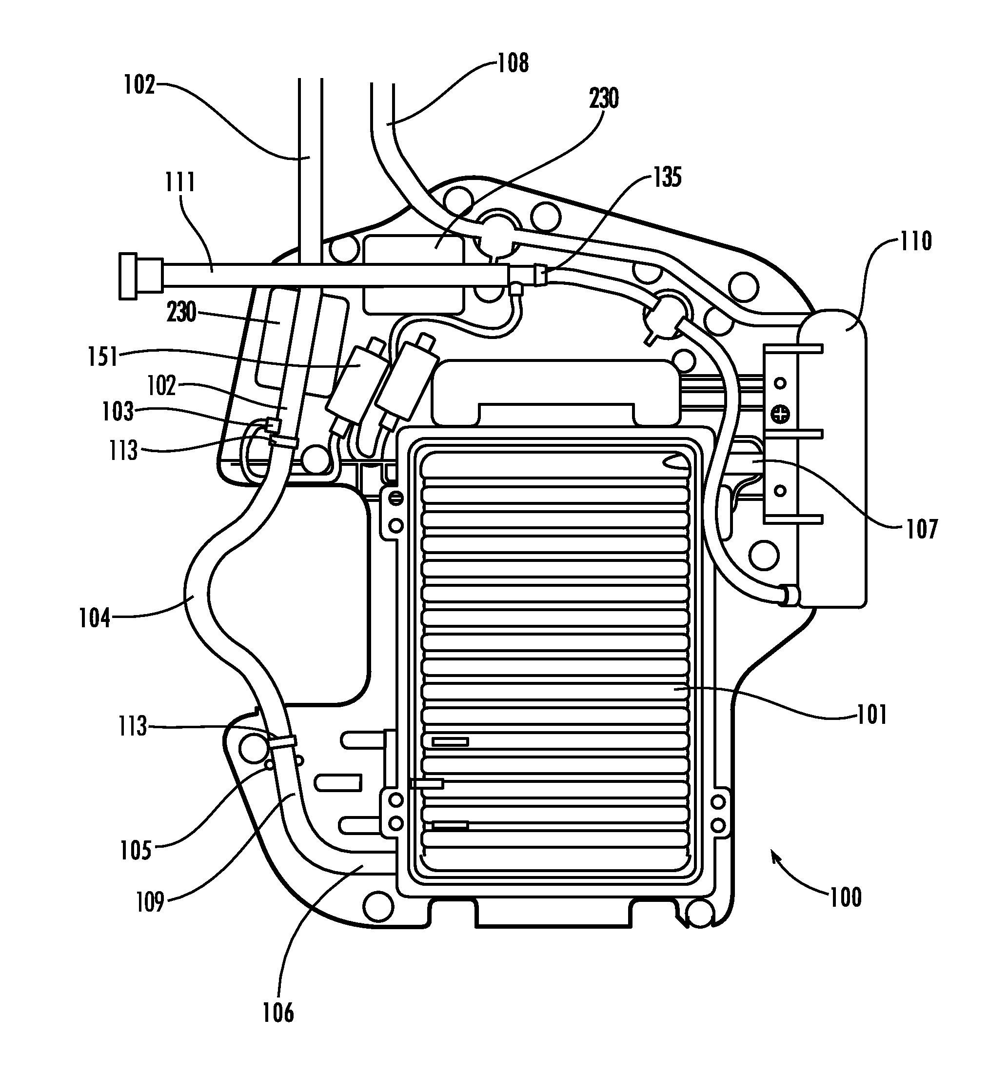
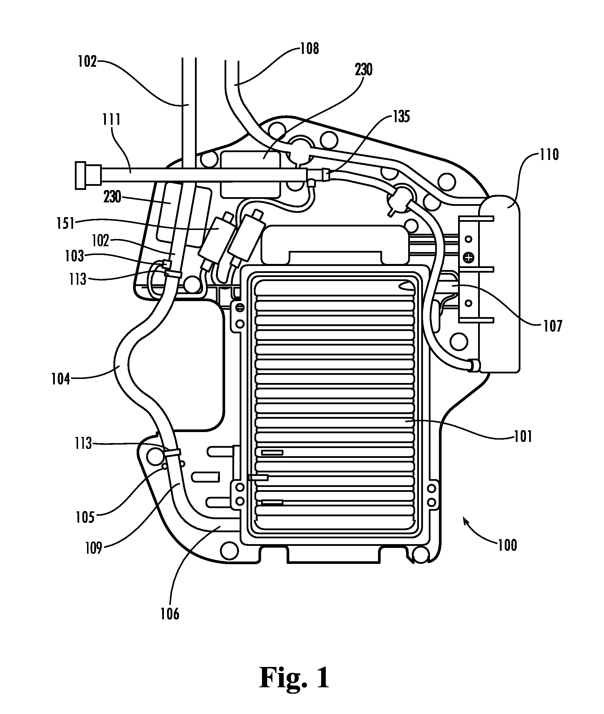
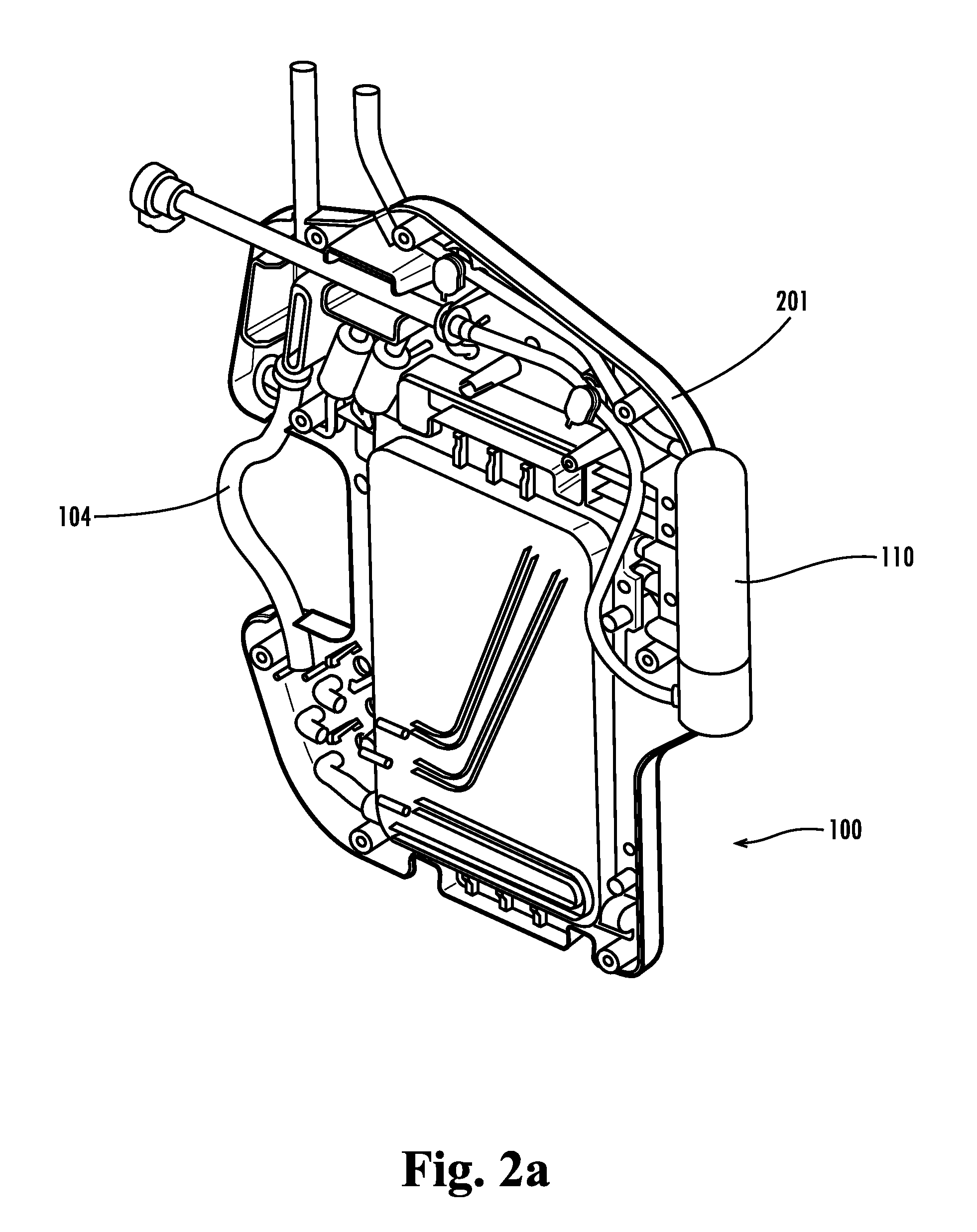
A pump system selectably controls the temperature, flow rate, flow volume, and flow pressure of a fluid being infused into a patient's body. The pump system includes a cartridge and components that removably connect with a pump housing and corresponding components, providing simple attachment of the cartridge to the pump housing. The pump housing includes a pressure sensor, a bubble detector, and a temperature sensor on a first side of the pump housing, and an engaging actuator and a central controller. The cartridge includes on a first side a heat exchanger, a pressure receptor correspondingly aligned with the pressure sensor, and a detector interface correspondingly aligned with the bubble detector and temperature sensor. Upon aligning the cartridge with the pump housing and actuating the engaging actuator, the pressure receptor communicates with the pressure sensor and the detector interface aligns with the bubble detector and temperature sensor.

Description

RELATED APPLICATION[0001]This application is a continuation-in-part of U.S. patent application Ser. No. 11 / 082,260 filed Mar. 17, 2005, which is incorporated by reference in its entirety herein.STATEMENT REGARDING FEDERALLY SPONSORED RESEARCH OR DEVELOPMENT[0002]This invention was made possible at least in part with the assistance of US Grant No. DAMD 17-02-01-0700 awarded by the United States Army, and the government may have certain rights therein.FIELD OF THE INVENTION[0003]The present invention is directed to an infusion device having a disposable cartridge for warming and / or cooling fluid that connects with a pump housing and allows for simple, accurate control of infusion flow rates and / or infusion pressures.BACKGROUND[0004]Fluid required in treating a patient must often be stored in comparatively cool to cold temperatures with respect to the patient's body temperature. This often refrigerated storage is necessary to preserve the fluids in a state so the function and integrity...

Claims


Application Information

Patent Timeline
IPC IPC(8): A61M31/00A61M1/00
CPCA61M1/0281A61M5/16831A61M5/36A61M5/365A61M5/172A61M2205/127A61M2206/10A61M2206/14A61M5/44
Inventor SMISSON, HUGH F.CARTLEDGE, RICHARD G.FIELD, DAVID C.JAECKLEIN, WILLIAM J.KOLTZ, MICHAEL L.LEWIS, HARVEY A.RAINIER, BRADFORD J.STAFFORD, ROLAND T.
Owner SMISSON CARTLEDGE BIOMEDICAL
Why Eureka
Try Eureka