
Toner and method of manufacturing the same, two-component developer, developing apparatus, and image forming apparatus

Inactive Publication Date: 2008-07-10
SHARP KK
View PDF10 Cites 47 Cited by
  • Summary
  • Abstract
  • Description
  • Claims
  • Application Information

AI Technical Summary

Benefits of technology

[0022]An object of the invention is to provide a toner excellent in temporal stability, which is capable of maintaining good cleaning property stably for a long period of time and whose surface is provided with a coating layer having an effect of preventing toner aggregation. Another object of the invention is to provide a method of manufacturing the toner just stated. Still another object of the invention is to provide a two-component developer, a developing apparatus, and an image forming apparatus, which employ the toner stated above.

Problems solved by technology

In this state, adherence of the fine powder to the toner particles is so small that when the toner is used for a long term, the fine particles are desorbed from the toner particles, for example, by agitating the developer inside a developer container, thus causing difficulty in maintaining for a long time an effect of improved cleaning property owing to the mixing of the fine particles.
In the toners disclosed in JP-A 3-100660 and JP-B2 3365018, however, the resin fine particles cannot be sufficiently prevented from being desorbed from the toner particles upon agitating the developer inside the developer container, thus failing to solve the problem of decrease in cleaning property for a long-term use.
In the toner disclosed JP-A 10-307424, however, the surface coverage of the nonspherical particles with the chargeable resin particles is 5% to 50% and in addition, the chargeable resin particles are firmly adhered to only the convex surfaces of the nonspherical particles, incurring a problem that low melting point components contained in the nonspherical particles leach out to cause the toner to aggregate.
In the method, the crystalline polyester resin easily causes blocking of toner powders and it is thus difficult to maintain the storage stability.
Furthermore, it is also difficult to maintain the storage stability of fixed toner image.
In forming the core-shell structure of capsule toner mentioned above, it is difficult to form a uniform core-shell bonded interface.
Strength of core-shell interface in the capsule toner of conventional design has not reached to a sufficient level.
This accelerates deterioration of chargeability of the developer.
There has been therefore concern that the developing roll, the photoreceptor, and the carrier are more easily contaminated, which leads to a decrease in quality of formed images.

Method used


Image

  • Toner and method of manufacturing the same, two-component developer, developing apparatus, and image forming apparatus
  • Toner and method of manufacturing the same, two-component developer, developing apparatus, and image forming apparatus
  • Toner and method of manufacturing the same, two-component developer, developing apparatus, and image forming apparatus

Examples


example 1

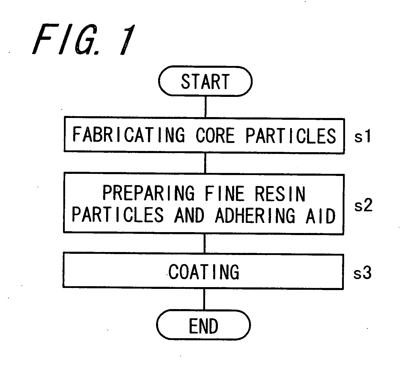
Step of Fabricating Core Particles

[0178]Raw material monomers were synthesized with the aid of catalyst to obtain polyester resin. The raw material monomers were specifically 400 parts of polyoxypropylene(2.0)-2,2-bis(4-hydroxyphenyl)propane, 380 parts of polyoxyethylene(2.0)-2,2-bis(4-hydroxyphenyl)propane, and 330 parts of terephthalic acid. The catalyst was specifically 3 parts of dibutyltin oxide. The polyester resin thus obtained had a glass transition temperature (Tg) of 64° C. and a softening temperature (Tm) of 95° C. And then, as a colorant, copper phthalocyanine (C.I. pigment blue 15:3) was added to the polyester resin. A thus-obtained material was melt-kneaded for 40 minutes by a kneader set at 140° C. As a result, a master batch was obtained which contains 40% by weight of the colorant. Note that polyoxypropylene(2.0)-2,2-bis(4-hydroxyphenyl)propane is an adduct in which 2.0 mol of propylene oxide is added on average to 1.0 mol of 2,2-bis(4-hydroxyphenyl)propane, and pol...

example 2

[0186]A toner of Example 2 was obtained in the same manner as Example 1 except that the step of preparing the fine resin particles and the adhering aid and the step of coating were modified as follows. The toner of Example 2 had a volume average particle size of 7.3 μm and a coefficient of variation of 26.

[0187](Step of Preparing Fine Resin Particles and Adhering Aid)

[0188]Using a homogenizer: Polytron PT-MR3100 (trade name) manufactured by Kinematica Inc., 20 parts of fine particles of styrene-methyl methacrylate copolymer having a volume average particle size of 0.4 μm and 80 parts of ethanol serving as the adhering aid were mixed with each other by agitation at a rotational speed of 8,000 rpm for 20 minutes, thereby preparing a coating solution which contains 20% by weight of the fine resin particles having a volume average particle size of 0.4 μm. To be specific, the fine particles of styrene-methyl methacrylate copolymer were MP-5000 (trade name) manufactured by Soken Chemical ...

example 3

[0191]A toner of Example 3 was obtained in the same manner as Example 1 except that the used fine resin particles were fine resin particles of styrene-methyl methacrylate copolymer having a volume average particle size of 0.2 μm and a glass transition temperature (Tg) of 102° C., which had been obtained by polymerizing styrene and methyl methacrylate. The toner of Example 3 had a volume average particle size of 7.1 μm and a coefficient of variation of 25.


PUM


Abstract

A toner excellent in temporal stability is provided which toner is capable of maintaining good cleaning property stably for a long period of time and whose surface is provided with a coating layer having an effect of preventing toner aggregation. There are also provided a method of manufacturing the toner, a two-component developer, a developing apparatus, and an image forming apparatus. The toner has a core particle containing a binder resin and a colorant and a coating layer which contains fine resin particles and are formed on surfaces of the core particles. The coating layers are formed by partially fusing the fine resin particles to at least either the core particle or adjacent fine resin particles.

Description

CROSS-REFERENCE TO RELATED APPLICATION[0001]This application claims priority to Japanese Patent Application Nos. 2007-001796, which was filed on Jan. 9, 2007, and 2007-238473, which was filed on Sep. 13, 2007, the contents of which are incorporated herein by reference in its entirety.BACKGROUND OF THE INVENTION[0002]1. Field of the Invention[0003]The present invention relates to a toner for use in developing a latent image in an image forming apparatus which employs the electrophotographic or electrostatic printing system, and further, to a method of manufacturing the toner, a two-component developer, a developing apparatus, and an image forming apparatus.[0004]2. Description of the Related Art[0005]Toners for visualizing a latent image have been used in various image forming processes which include, as one known example, an electrophotographic image forming process.[0006]An image forming apparatus for forming images through the electrophotographic system includes a photoreceptor, a...

Claims


Application Information

Patent Timeline
IPC IPC(8): G03G15/06G03G9/087
CPCG03G9/0808G03G9/081G03G2215/0602G03G15/08G03G9/0825
Inventor KAWASE, YOSHITAKA
Owner SHARP KK
Learn More