Humidity Tolerant Electro-Optic Device

a technology of electro-optic devices and humidity tolerance, applied in the direction of optical waveguide light guides, instruments, coatings, etc., can solve the problems of temperature-induced bias drift and/or dc drift, dc drift, dc drift, etc., and achieve the effect of improving performan

Active Publication Date: 2008-07-17
LUMENTUM OPERATIONS LLC
View PDF38 Cites 13 Cited by
  • Summary
  • Abstract
  • Description
  • Claims
  • Application Information

AI Technical Summary

Benefits of technology

[0018]The instant inventors have found that electro-optic devices having a separate bias electrode structure, as for example disclosed in US Patent Application Publication No. 2006 / 0023288, may exhibit improved performance if a thin buffer layer is provided between the bias signal electrode(s) and the substrate.

Problems solved by technology

Unfortunately, Z-cut LiNbO3 modulators are also known to suffer more from charge build up problems, which for example, may lead to temperature induced bias drift and / or DC drift.
DC drift, also termed bias drift, is particularly problematic when the modulator includes a buffer layer 150 disposed between the substrate 110 and the signal electrode 140.
Unfortunately, in order to accommodate both electrode structures, the length of the modulator is significantly increased.
In addition, this design is not ideal for Z-cut LiNbO3, wherein the waveguides are located directly below the bias electrodes, because the highly conductive bias electrode material (e.g., Au) may introduce significant optical loss.
Unfortunately, it can be difficult to quantitatively control the introduction of the doping elements with a high reproducibility.
Furthermore, water may be absorbed by the conductive buffer layer, changing its properties.
As is well known in the art, the presence of high magnitude electric fields and high humidity often results in corrosion of electro-optic devices.
Galvanic corrosion, which results from the difference in electrochemical potentials of dissimilar metals, can create a conductive deposit between the surface RF electrodes, which causes current leakage, short circuit, or peeling of the RF electrodes.
While these methods do suppress galvanic corrosion, electro-migration corrosion can still occur.
Electro-migration corrosion occurs when a large DC voltage is applied across closely-spaced electrodes (e.g., gold RF electrodes) in the presence of water or a high humidity level.
Similar to galvanic corrosion, electro-migration corrosion negatively impacts the performance and reduces the service life of electro-optic devices.
However, the coatings negatively impact the RF properties of the RF electrode, and hermetic packaging adds cost to the modulator.

Method used


Image

  • Humidity Tolerant Electro-Optic Device
  • Humidity Tolerant Electro-Optic Device
  • Humidity Tolerant Electro-Optic Device

Examples


Embodiment Construction

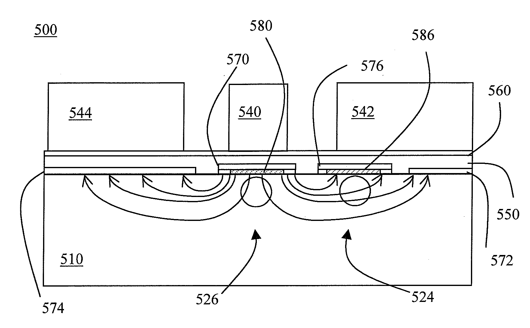
[0056]Referring to FIG. 5a, there is shown a sectional view of an electro-optic device in accordance with one embodiment of the instant invention. The electro-optic device 500 includes a substrate 510, first 524 and second 526 optical waveguides, an RF signal electrode 540, RF ground electrodes 542, 544, an upper buffer layer 550, a bleed layer 560, first 570 and second 576 bias signal electrodes, bias ground electrodes 572, 574, and a lower buffer layer 580, 586.

[0057]In this embodiment, the substrate 510 is fabricated from an electro-optic material such as Z-cut lithium niobate (LiNbO3). Alternatively, the substrate is fabricated from another electro-optic material, such as Z-cut lithium tantalite (LiTaO3). The width, length, and thickness of the substrate 510 typically vary with the type of electro-optic device. For example, substrates for conventional Mach-Zehnder modulators are often about 40 mm long, 2 mm wide, and 1 mm thick. Of course, other dimensions are also possible.

[005...


PUM


Abstract

The invention relates to an electro-optic modulator structure containing an additional set of bias electrodes buried within the device for applying bias to set the operating point. Thus the RF electrodes used to modulate incoming optical signals can be operated with zero DC bias, reducing electrode corrosion by galvanic and other effects that can be present in non-hermetic packages. The bias electrodes are at least partially separated from the substrate with a buffer layer, which in one embodiment has a small amount of conductivity. This conductive buffer layer reduces optical loss from the bias electrodes and also reduces DC drift.

Description

CROSS-REFERENCE TO RELATED APPLICATIONS[0001]This application claims priority from U.S. Provisional Patent Application Ser. No. 60 / 884,653 filed Jan. 12, 2007, which is hereby incorporated by reference for all purposes.TECHNICAL FIELD[0002]The present invention relates generally to electro-optic devices and, more specifically, to electro-optic devices used in fiber-optic telecommunications.BACKGROUND OF THE INVENTION[0003]Electro-optic devices are frequently used in fiber-optic telecommunication systems to manipulate optical signals. In general, these electro-optic devices include at least one optical waveguide formed from and / or in an electro-optic material. When an electric field is generated in the electro-optic material, the refractive index of the optical waveguide(s) change and the optical signal propagating there through can be altered. Some examples of common electro-optic devices used in telecommunication systems include optical modulators, optical switches, optical coupler...

Claims


Application Information

Patent Timeline
Patent Type & Authority Applications(United States)
IPC IPC(8): G02B6/12B05D5/12
CPCG02F1/0356G02F1/0316
Inventor KISSA, KARLMINFORD, WILLIAM J.DRAKE, GLEN
Owner LUMENTUM OPERATIONS LLC
Why Eureka
Try Eureka