Methods of operating an electromagnet of an ion source

an ion source and electromagnet technology, applied in the direction of fluid pressure measurement, instruments, ion beam tubes, etc., can solve the problems of inability to transparently observe the ion optics, the compensation method has several limitations, and the distribution of ion current density is not uniform

Active Publication Date: 2008-07-31
VEECO INSTR
View PDF51 Cites 39 Cited by
  • Summary
  • Abstract
  • Description
  • Claims
  • Application Information

AI Technical Summary

Benefits of technology

[0010]Embodiments of the invention are directed generally to methods for modifying the performance of an ion source to generate an ion beam with tailored operating characteristics. Generally, the ion source may include a plasma discharge vessel, a cup-shaped re-entrant vessel projecting into the plasma discharge vessel, at least one electromagnet, and at least one tubular pole piece. The electromagnet and tubular pole piece may be coaxially arranged inside the re-entrant vessel. Each electromagnet is adapted to induce a magnetic field for changing a shape of the plasma inside the plasma discharge vessel.

Problems solved by technology

This introduces non-uniformities into the ion current density distribution of the broad ion beams generated by such conventional ion sources.
However, this compensation method has several limitations.
Variations in the transparency of the ion optics cannot compensate for variations in the plasma density profile for different ion source operating conditions (i.e., RF power, beam voltage and current, gas type and pressure), for any time dependence of these factors between system maintenance periods, or for variations in source and ion optics.
Additionally, localized variations in the plasma radial and / or azimuthal density distributions typically limit the uniformity of the IBE process.
The transparency of the grid optics cannot be easily modified to compensate for this dependence on operating conditions.
However, the ion source may require an adjustment to eliminate non-uniformities observed in the ion beam density.

Method used


Image

  • Methods of operating an electromagnet of an ion source
  • Methods of operating an electromagnet of an ion source
  • Methods of operating an electromagnet of an ion source

Examples


example 1

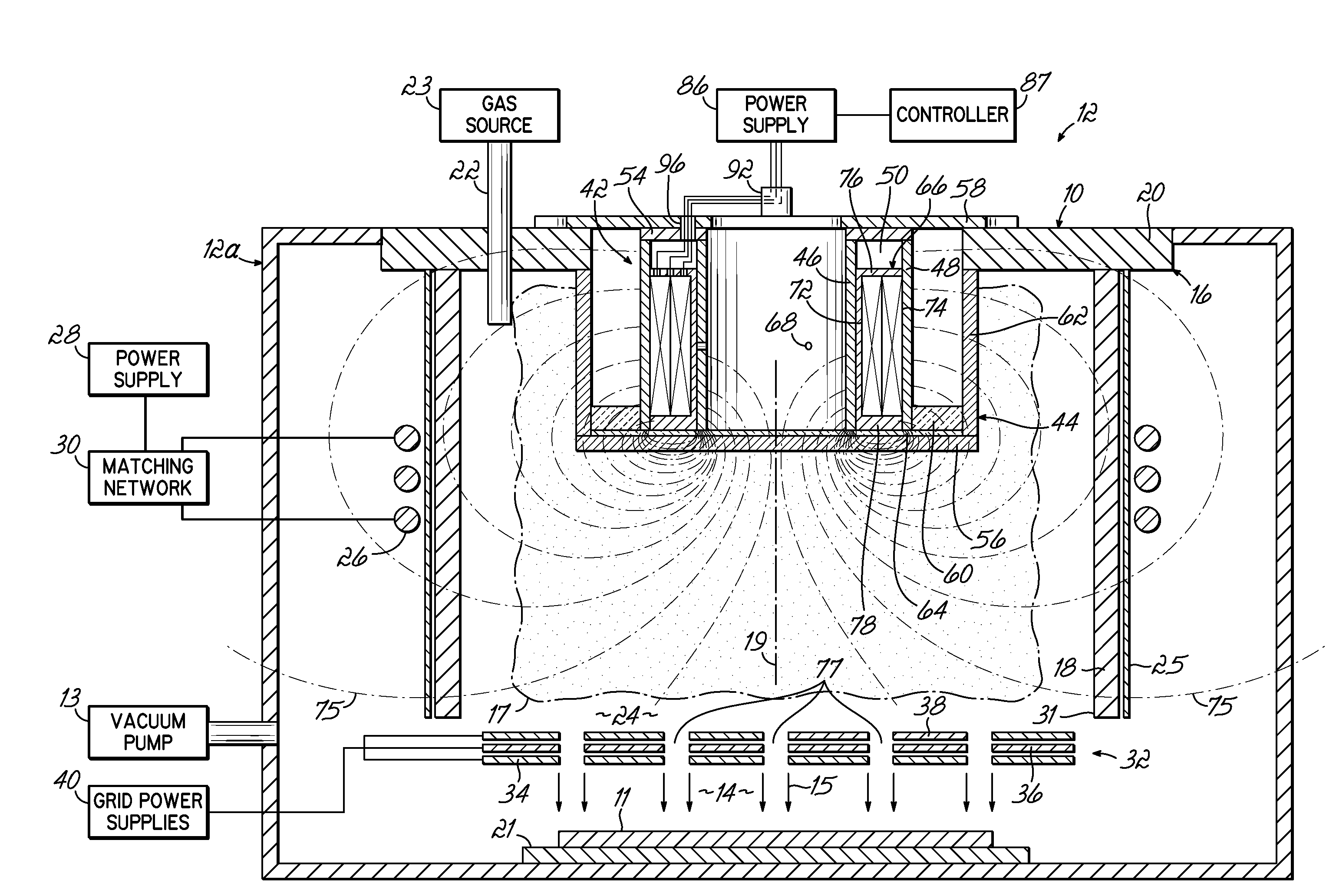
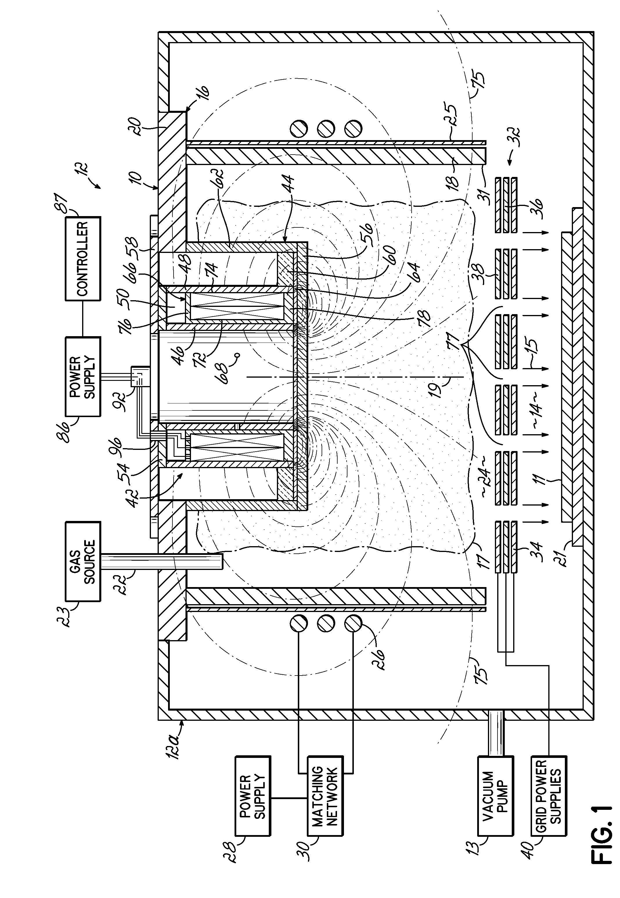
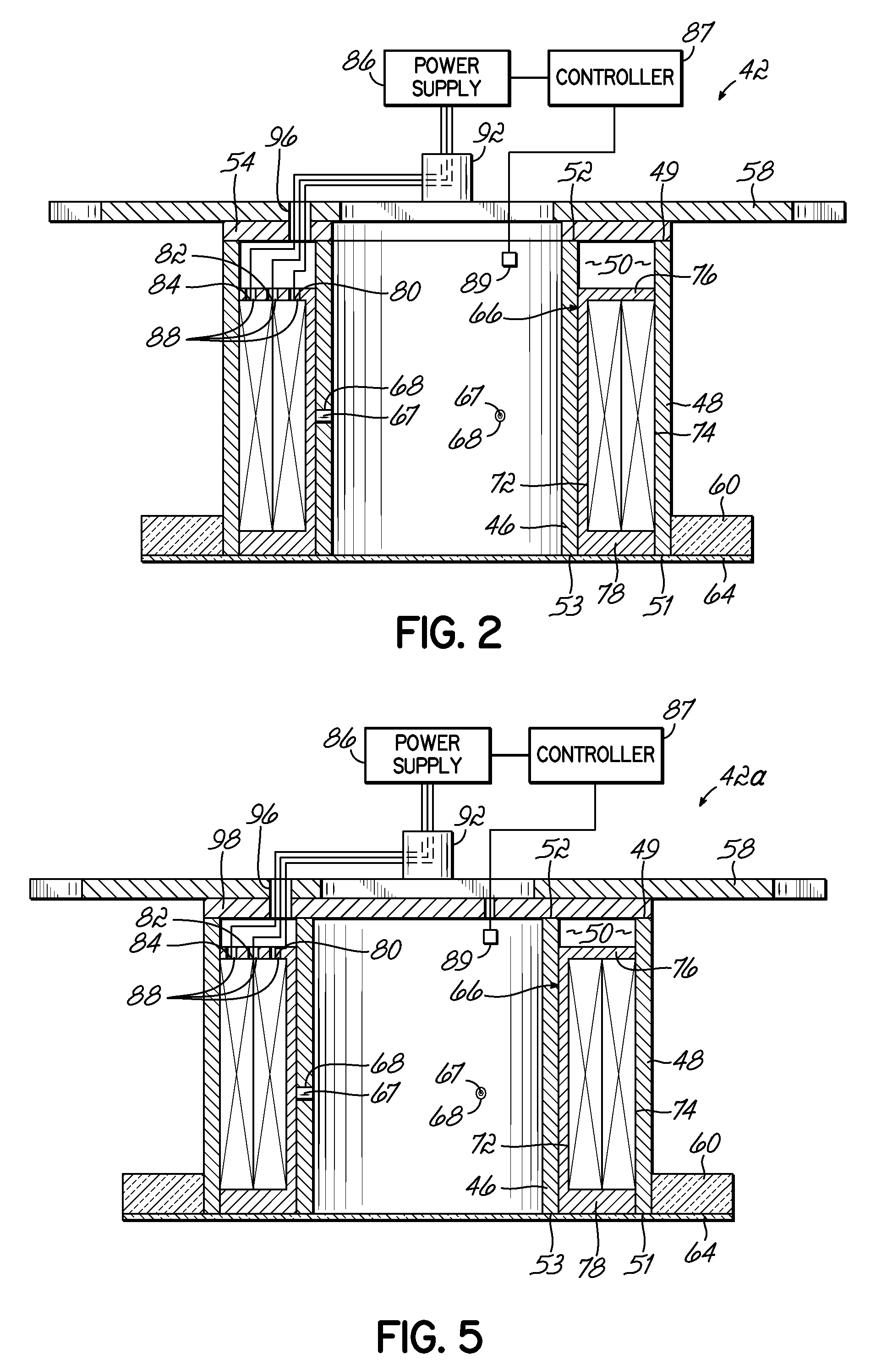
[0085]An ion source having an electromagnet assembly, otherwise substantially identical to electromagnet 42b (FIG. 6) but with each of the inner and outer coils including a single coil of 970 turns, was equipped with an ammeter between the coil of the radially innermost electromagnet and power supply for purposes of measuring the current supplied to the radially outermost coil of this electromagnet 42b. The coil of the radially outermost electromagnet was disconnected from the power supply so that only the innermost coil of the electromagnet 42b was energized. An electrical probe was inserted into the beam and situated in the substrate plane perpendicular to the beam incidence direction. A voltage was measured from the electrical probe, which was charged under the substrate processing conditions. This voltage was considered as a measure of the broad ion beam neutralization. A 1200 V, 650 mA beam of positively charged ions was extracted from an argon gas plasma. While propagating tow...

example 2

[0089]As evidence that the operation of the electromagnet under controlled conditions does not degrade the ion beam directionality, the “local divergence angle” of the angular distribution of the ions was evaluated for optimum electromagnet current settings at different positions in the beam and compared with equivalent results obtained without the electromagnet for the same process parameters. The “local divergence angle” was determined by etching a substrate beneath a masking aperture and measuring the size of the etch spot, essentially as described by J. R. Kahn, et al, J. Vac. Sci. Technol. A14(4), July / August 1996, p. 2106-2112 (ref. FIG. 1), except that a silicon dioxide coated silicon wafer was used as the substrate and a nanospectrophometric measurement apparatus (Nanometrics Nanospec™ 8000) capable of high resolution etch depth and lateral position measurement was used to determine the etch depth profile. The disclosure of this publication is hereby incorporated by referenc...

example 3

[0091]A series of ion etch profiles, which have been normalized for presentation, were generated using the ion source and operating parameters (except for the current applied to the electromagnet) of Example 1 and are shown in FIG. 9. With no current applied to the coils of the electromagnet (and therefore no field strength), the plasma density distribution and the distribution of plasma ion flux are characterized by a convex profile, which is reflected in the ion etch profile of curve 200. At a relatively low field strength, BL, the plasma density distribution and the distribution of plasma ion flux increase in convexity with increasing field strengthen, as reflected in the ion etch profile of curve 210. At a relatively high field strength, BH, the plasma density distribution and the distribution of plasma ion flux changes shape to become more concave with increasing field strength. Eventually, the plasma density distribution and the distribution of plasma ion flux change to a conc...


PUM

PropertyMeasurementUnit
pressuresaaaaaaaaaa
vacuum pressureaaaaaaaaaa
frequencyaaaaaaaaaa

Abstract

Methods of operating an electromagnet of an ion source for generating an ion beam with a controllable ion current density distribution. The methods may include generating plasma in a discharge space of the ion source, generating and shaping a magnetic field in the discharge space by applying a current to an electromagnet that is effective to define a plasma density distribution, extracting an ion beam from the plasma, measuring a distribution profile for the ion beam density, and comparing the actual distribution profile with a desired distribution profile for the ion beam density. Based upon the comparison, the current applied to the electromagnet may be adjusted either manually or automatically to modify the magnetic field in the discharge space and, thereby, alter the plasma density distribution.

Description

CROSS-REFERENCE TO RELATED APPLICATIONS[0001]The present application is a continuation-in-part of U.S. patent application Ser. No. 11 / 678,979, filed Feb. 26, 2007, which is a continuation-in-part of U.S. patent Ser. No. 10 / 772,132, now U.S. Pat. No. 7,183,716, filed Feb. 4, 2004, the disclosure of each of which is hereby incorporated herein by reference in its entirety. The present application claims the benefit of U.S. Provisional Application Ser. No. 60 / 891,669, filed Feb. 26, 2007, the disclosure of which is hereby incorporated herein by reference in its entirety.FIELD OF THE INVENTION[0002]The invention relates to methods of operating an electromagnet of an ion source to generate an ion beam with tailored operating characteristics.BACKGROUND OF THE INVENTION[0003]Ion beam processing systems are used in a variety of applications for modifying the properties of a substrate during the fabrication of thin film devices, such as semiconductor and data storage devices. In particular, e...

Claims


Application Information

Patent Timeline
Patent Type & Authority Applications(United States)
IPC IPC(8): G01L21/30B44C1/22
CPCH01J27/18H01J37/08H01J37/3053H01L21/67069H01J2237/083H01J2237/24542H01J2237/061
Inventor HAYES, ALAN V.YEVTUKHOV, RUSTAMKANAROV, VIKTORDRUZ, BORIS L.
Owner VEECO INSTR
Why Eureka
Try Eureka