
Numerical full well capacity extension for photo sensors with an integration capacitor in the readout circuit using two and four phase charge subtraction

Active Publication Date: 2008-07-31
TELEDYNE SCI & IMAGING
View PDF23 Cites 11 Cited by
  • Summary
  • Abstract
  • Description
  • Claims
  • Application Information

AI Technical Summary

Benefits of technology

[0015]The method for increasing the full well capacity in a detector circuit using four phase charge subtraction includes, in a first phase, integrating a signal with a first capacitor and sampling the signal with a second capacitor, in a second phase, integrating the signal with the second capacitor and sampling the signal with the first capacitor, in a third phase, reversing the polarity of the first and second capacitors, integrating the signal with the first capacitor, and sampling the signal with the second capacitor, and in a fourth phase, reversing the polarity of the first and second capacitors, integ

Problems solved by technology

This ideal situation can only be approximated by any real detection system, and in practice most systems are restricted to specific lighting and / or operating conditions to satisfy this requirement over a limited range.
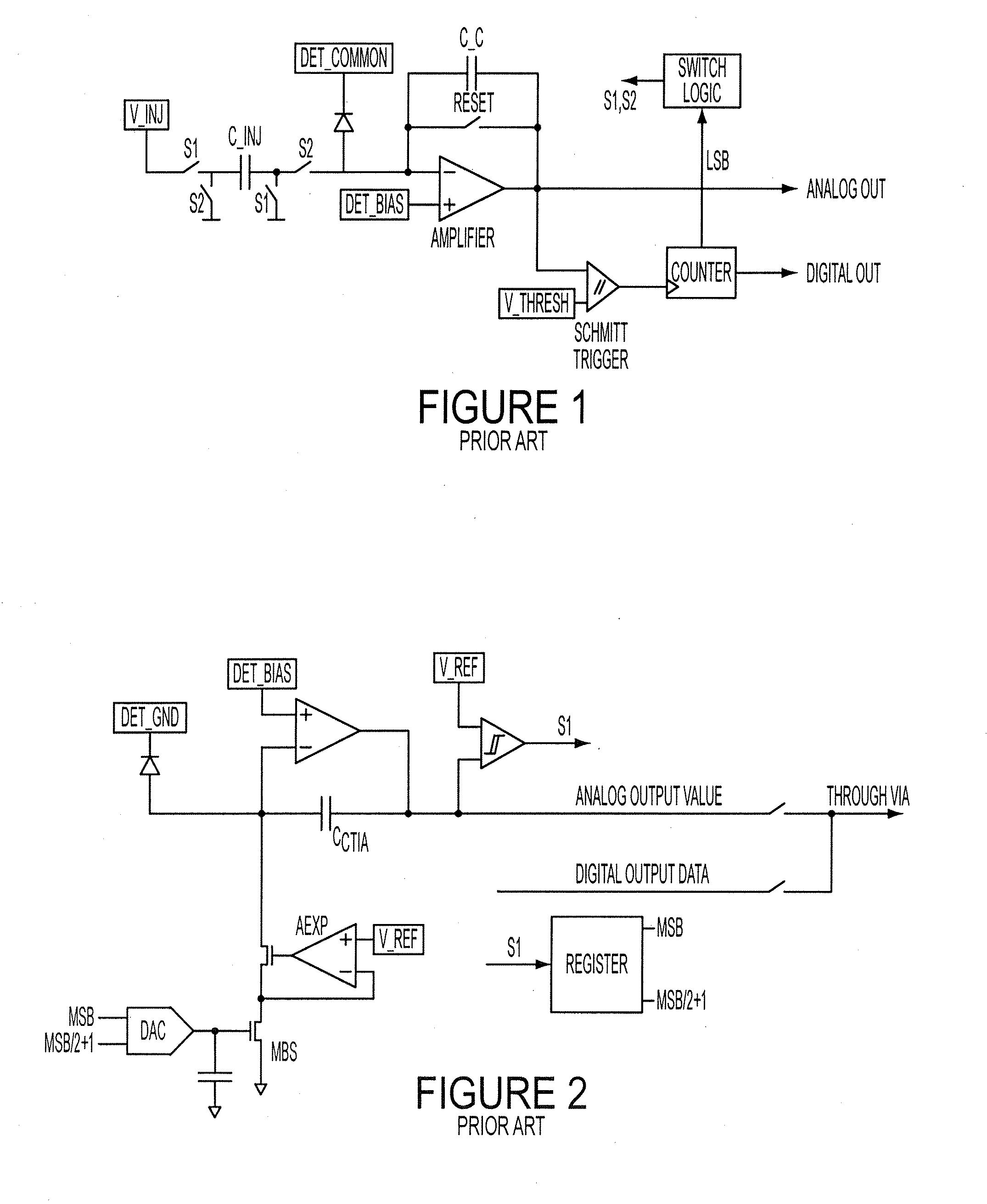
The approach is not suited for Direct Injection (DI), Buffered Direct Injection (BDI) or floating diffusion type front end circuits with a high impedance integration node.
Second, an additional capacitor has to be connected to the input node, which increases the size and noise of the front end circuit.
However, one disadvantage of using the current sink is that it requires a large unit cell in order to achieve low noise performance.
Since technology is moving towards smaller photo detection systems, this prior art approach is less favorable.
In photo detection applications with very high backgrounds and / or high signal levels such as long wave infrared imagers, the physically achievable full well capacity of one individual pixel of an imaging array is typically too small to integrate all charge carriers that are generated per 1 frame time.
However, practical limitations of pixel size, achievable specific capacitance per area and maximum voltage, tolerated by the integrated circuit process, nevertheless make it impossible to capture all of the physically available information with these techniques that scale poorly with process generations.
As such, the number of detector sites is limited, as is the minimum spacing between detector sites, thereby limiting the achievable image resolution.
If only a part of the generated signal charge can be integrated, a part of the physically available information would be lost in the detection process.

Method used


Image

  • Numerical full well capacity extension for photo sensors with an integration capacitor in the readout circuit using two and four phase charge subtraction
  • Numerical full well capacity extension for photo sensors with an integration capacitor in the readout circuit using two and four phase charge subtraction
  • Numerical full well capacity extension for photo sensors with an integration capacitor in the readout circuit using two and four phase charge subtraction

Examples


Embodiment Construction

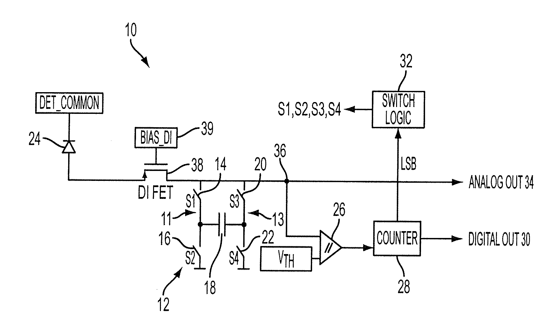
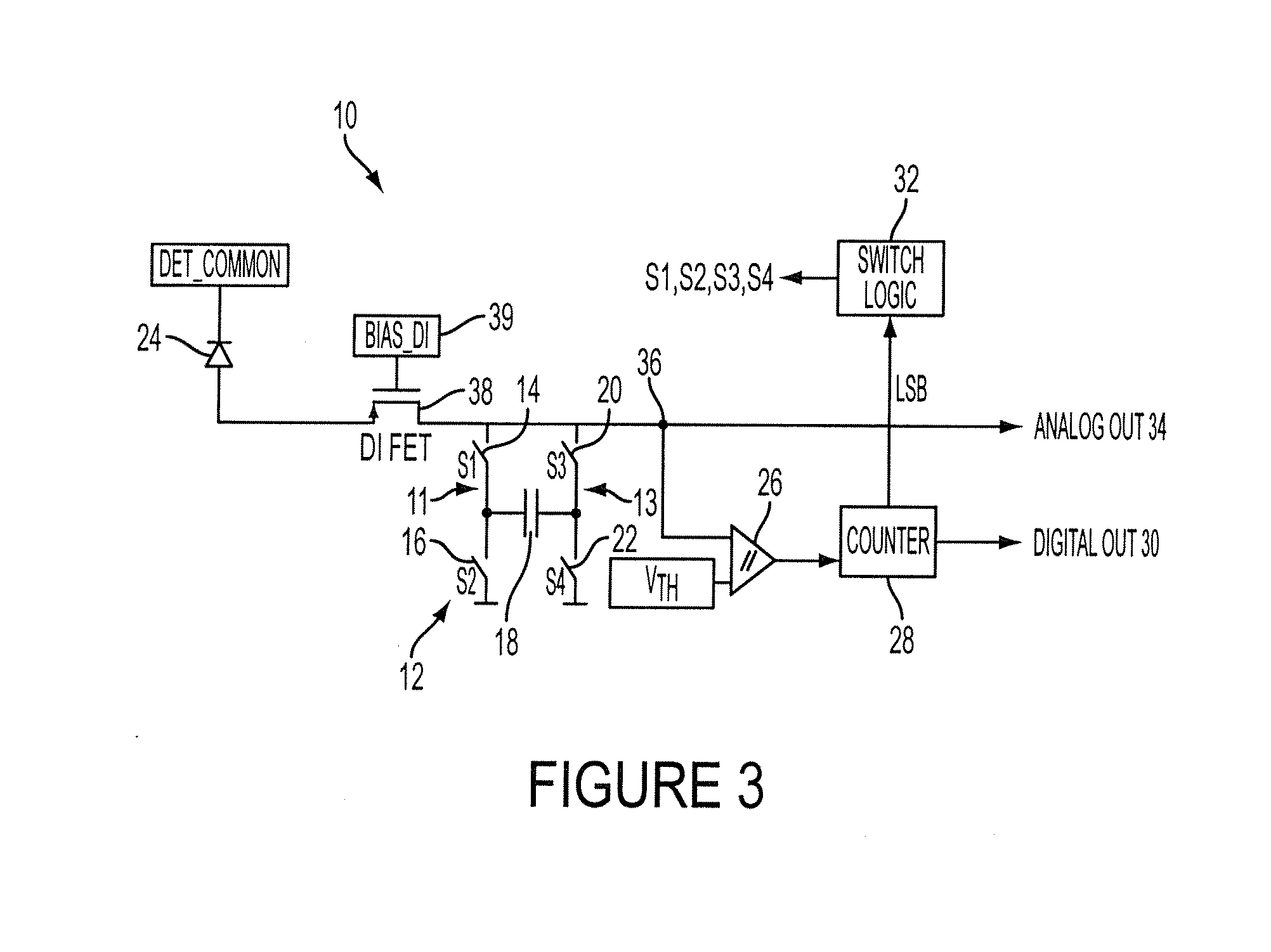
[0034]FIG. 3 is a circuit diagram of a unit cell digitizer 10 with Direct Injection (DI) type front end, according to an embodiment of the invention. The unit cell digitizer 10 may include an integration capacitor 18 coupled to a photodiode 24 and a DI FET 38 via a switch matrix 12. The switch matrix 12 has two switches 14 and 16 on one side 11 of the integration capacitor 18 and two switches 20 and 22 on the other side 13.

[0035]The DI FET 38 may be either N or P type depending on whether electrons (N type DI transistor) or holes (P type DI transistor) are read out by the unit cell digitizer 10. The DI FET 38 may drain charge from the photodiode 24 by offering a low impedance path onto the integration capacitor 18. The DI FET 38 keeps the voltage on the source constant but allows current to flow off with very low resistance into a high impedance node 36. The bias voltage on the DI FET 38 is Bias_DI 39.

[0036]The switch matrix 12 may allow electronic “rotation” of the integration capa...


PUM


Abstract

A detector circuit having an integration capacitor coupled to an amplifier via a switch matrix and a comparator coupled to the amplifier, the integration capacitor operable in two or more phases, the switch matrix is configured to phase switch the integration capacitor, the comparator triggers the phase switch when the output voltage of the amplifier passes the threshold voltage of the comparator.

Description

BACKGROUND OF THE INVENTION[0001]1. Field of the Invention[0002]The invention relates generally to photo sensors. More particularly, the invention relates to numerical full well capacity extension for photo sensors with an integration capacitor in the readout circuit using two and four phase charge subtraction.[0003]2. Description of Related Art[0004]Ideally, an electronic photo detection system should translate the incoming photon signal into an electronic signal with maximum fidelity, for example, without adding noise, signal distortion or saturation towards high intensities. This ideal situation can only be approximated by any real detection system, and in practice most systems are restricted to specific lighting and / or operating conditions to satisfy this requirement over a limited range. The wider this operating range, the more powerful the sensor system and the less the restrictions that have to be applied to the operating conditions.[0005]Recent advances in photo detection sy...

Claims


Application Information

Patent Timeline
IPC IPC(8): G01R27/26H04B1/10
CPCH04N3/1568H04N5/3745H04N5/357H04N25/60H04N25/772
Inventor LAUXTERMANN, STEFAN C.
Owner TELEDYNE SCI & IMAGING
Learn More