Solid stick compositions comprising vinyl ester

a technology of vinyl ester and composition, which is applied in the direction of rail wetting/lubrication, rail lubrication, transportation and packaging, etc., can solve the problems of high noise level, uneven wear of mechanical components, and high noise level of steel-rail and steel-wheel transportation systems, so as to reduce wear and energy consumption, reduce consumption, and improve performan

Active Publication Date: 2008-07-31
L B FOSTER RAIL TECH INC
View PDF35 Cites 8 Cited by
  • Summary
  • Abstract
  • Description
  • Claims
  • Application Information

AI Technical Summary

Benefits of technology

[0035]The present invention provides solid stick compositions that exhibit the property of controlling friction between steel surfaces, and may be used to reduce wear and energy consumption in rail systems. Furthermore, the solid stick compositions of the present invention comprising vinyl ester resin, provide superior performance when compared to solid stick compositions comprising other resin compositions, including isophthalic and orthophthalic unsaturated polyester resins, halogenated unsaturated polyester resins, polyurethane-acrylic resin, polyester resin, polyethylene resin, or polypropylene resins of the prior art (for example as disclosed in U.S. Pat. No. 5,308,516, which is incorporated herein by reference). The solid stick compositions of the present invention have a reduced consumption and reduced wear compared to solid stick compositions known in the art. The solid stick compositions of the present invention therefore last longer and provide a cost advantage over know solid stick compositions.

Problems solved by technology

For example, many steel-rail and steel-wheel transportation systems including freight, passenger and mass transit systems suffer from the emission of high noise levels and extensive wear of mechanical components such as wheels, rails and other rail components such as ties.
The origin of such noise emissions, and the wear of mechanical components may be directly attributed to the frictional forces and behaviour that are generated between the wheel and the rail during operation of the system.
However, because the wheel and the rail are profiled, often misaligned and subject to motions other than strict rolling, the respective velocities at which the wheel and the rail move through the zone of contact are not always the same.
This is not possible on most fixed-axle railcars.
Sliding movement may also arise when traction is lost on inclines thereby causing the driving wheels to slip.
At creepage levels larger than about 1%, appreciable frictional forces are generated due to sliding, and these frictional forces result in noise and wear of components (H. Harrison, T. McCanney and J. Cotter (2000), Recent Developments in COF Measurements at the Rail / Wheel Interface, Proceedings The 5th International Conference on Contact Mechanics and Wear of Rail / Wheel Systems CM 2000 (SEIKEN Symposium No. 27), pp.
Unfortunately, it is often impossible to impart greater rigidity to a mechanical system, such as in the case of a wheel and rail systems used by most trains.
Alternatively, reducing the frictional forces between the wheel and the rail may greatly hamper adhesion and braking and is not always suitable for rail applications.
It is also known that, wear of train wheels and rails may be accentuated by persistent to and fro movement resulting from the presence of clearances necessary to enable a train to move over a track.
Corrugations increase noise levels beyond those for smooth rail-wheel interfaces and ultimately the problem can only be cured by grinding or machining the rail and wheel surfaces.
This is both time consuming and expensive.
However, this product exhibits poor retentivity under field conditions and must be reapplied at frequent intervals.
While a number of solid stick compositions in the prior art exhibit a range of friction characteristics, including lubricant compositions or compositions with a positive friction characteristic, a limitation of these solid stick compositions is their fast consumption rate.
Solid stick compositions must be repeatedly applied to the rail head or flange interface to ensure proper efficacy and such repeated application can result in substantial costs due to fast consumption rates of the sticks.

Method used


Image

  • Solid stick compositions comprising vinyl ester
  • Solid stick compositions comprising vinyl ester
  • Solid stick compositions comprising vinyl ester

Examples


example 1

Solid Stick Compositions

[0110]Examples of solid stick compositions comprising vinyl esters for testing were prepared using standard methods. Non-limiting sample compositions include those provided in Table 1. For each test, the resin component of the solid stick composition was varied. The resin components tested were as follows:[0111]1. Group I resins—resins commonly used in solid stick compositions known in the art: a halogenated isophthalic polyester (HETRON 99P™); an isophlatic polyester with aluminatrihydrate (DION FR 850-200™); and a halogenated polyester (POLYLITE 33441-00™),[0112]2. Group II resins—vinyl ester resins of the present invention: a bisphenol epoxy vinyl ester (DION VER 9100-00™) a brominated bisphenol epoxy vinyl ester (DION FR 9300™); a vinyl polyester (DION VPE 7100-06™); and an epoxy novolac-based vinyl ester (DERAKANE 470-300).

TABLE 1Samples of solid stick compositions comprising either 51% (w / w) or60% (w / w) of a lubricant (Molybdenum disulfide; MoS2)Additiv...

example 2

Stick Hardness Testing (D-Type Durometer)

[0114]The average hardness of solid stick compositions samples comprising the different resin components given in Example 1 and 51.87%, 20.82% or 10.00% (w / w) lubricant (molybdenum disulfide (MoS2)) were measured using a D-Type Durometer as would be know to one of skill in the art (ASTM D 2240 Standard Test Method for Rubber Property-Durometer Hardness). The method comprises pressing the Durometer against the sample, and measuring a material resistance force. The depth of the indentor was measured, which provides a measure of the material's hardness.

[0115]The results are given in Table 2 and indicate that solid stick composition samples comprising a vinyl ester resin (Group II resins) have a similar or lower average hardness compared with samples comprising halogenated polyester resins or isophthalic polyester resins (Group I resins) commonly used in known solid stick compositions.

TABLE 2Average hardness of solid stick composition samples com...

example 3

Stick Testing Apparatus (STA Testing)

[0116]A stick testing apparatus and test method was developed by Kelsan Technologies Corporation to measure solid stick composition consumption rates over a prolonged period of time and under variable abrasive surface conditions.

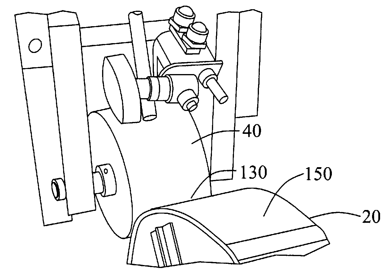
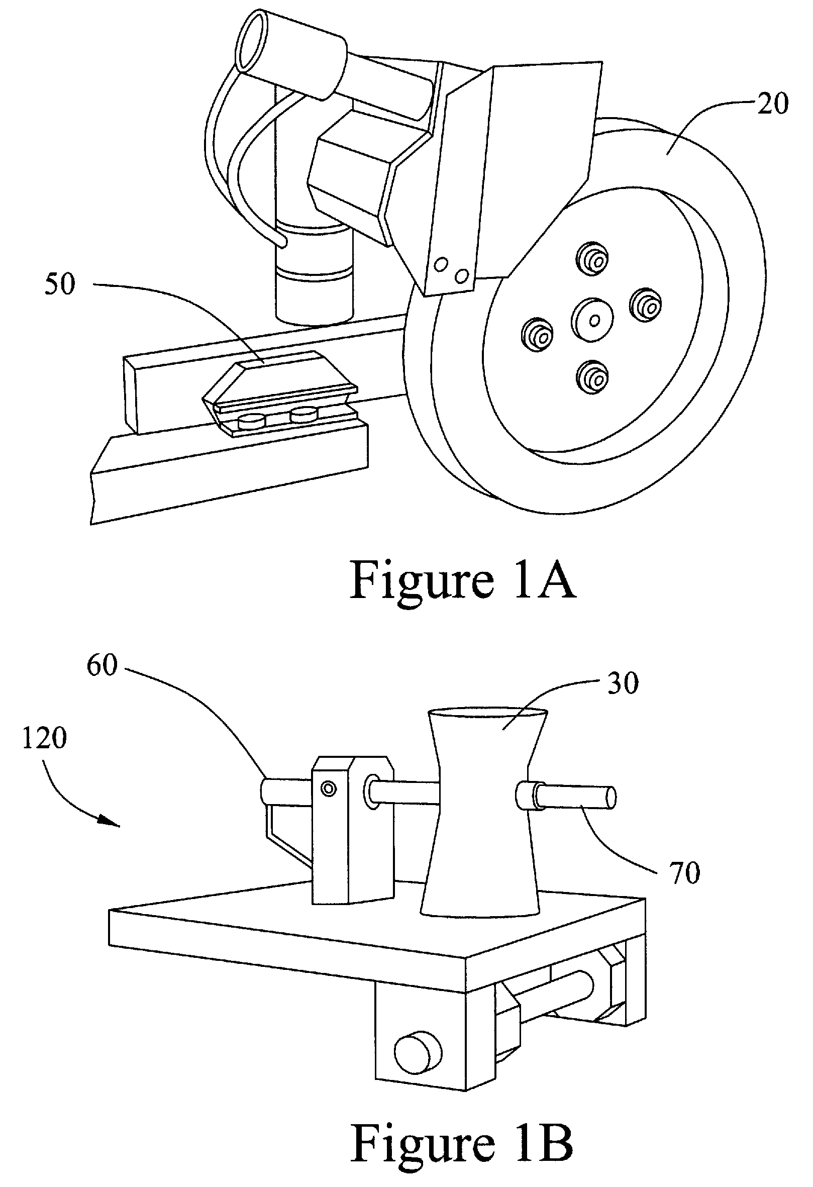
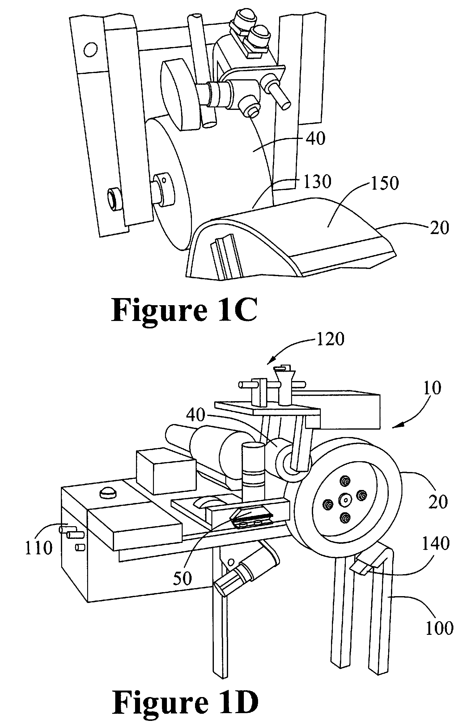
[0117]As shown in FIG. 1D, the Stick Testing Apparatus (10) comprises a frame (100) for mounting the following components: a standard stick mounting bracket (50), which receives a solid stick composition sample; an abrasion resistant steel main wheel (20) and a cooperating nib wheel (40); a sand applicator assembly (120); and a control box (110). As shown in FIG. 1B, the sand applicator assembly (120) comprises a sand trickier (30) into which sand is loaded, a sand trickier rod (70) for introducing sand onto the surface of the main wheel (40) and a sand trickier motor (60).

[0118]In use, the sand trickier (30) is loaded with sand, which may have been sieved to eliminate particles greater than a known size, for example, but...


PUM

PropertyMeasurementUnit
weight percentaaaaaaaaaa

Abstract

A solid stick composition for use on steel surfaces that are in sliding or rolling-sliding contact. The solid stick composition comprises a vinyl ester resin, for example, from about 20 to about 80 weight percent vinyl ester resin, a solid lubricant, for example from about 0 to about 80 weight percent lubricant, and optionally a friction modifier, for example from about 0 to about 40% weight percent friction modifier, or a combination of a solid lubricant and a friction modifier. The solid stick comprises at least one of the lubricant or the friction modifier. A method of controlling friction between a metal surface and a second metal surface by applying the solid stick composition to one or more than one of the metal surfaces is also disclosed as well as a method of reducing lateral force in a rail system comprising applying the solid stick composition onto a wheel or rail surface.

Description

FIELD OF INVENTION[0001]The present invention relates to solid sticks compositions. More specifically, the invention pertains to solid stick compositions comprising vinyl esters.BACKGROUND OF THE INVENTION[0002]The control of friction and wear of metal mechanical components that are in sliding or rolling-sliding contact is of great importance in the design and operation of many machines and mechanical systems. For example, many steel-rail and steel-wheel transportation systems including freight, passenger and mass transit systems suffer from the emission of high noise levels and extensive wear of mechanical components such as wheels, rails and other rail components such as ties. The origin of such noise emissions, and the wear of mechanical components may be directly attributed to the frictional forces and behaviour that are generated between the wheel and the rail during operation of the system.[0003]In a dynamic system wherein a wheel rolls on a rail, there is a constantly moving ...

Claims


Application Information

Patent Timeline
Patent Type & Authority Applications(United States)
IPC IPC(8): C10M125/00
CPCC08L63/00C10M2201/0613C10N2230/06C10M2201/0413C10M2201/061C10M2209/1023C10M2201/0653C10M2209/1033C10N2210/08C10M2201/0873C10M2207/1253C10M2201/087C10M2205/04C10M169/04B61K3/00C10M2215/06C10M2209/102C10M2201/065C10M2207/127C10M2209/0625C10M2201/0663C10M2209/062C10M2201/066C10M2201/041C10M2209/103C10N2210/06C10N2210/03C10N2260/08C10N2010/14C10N2030/06C10N2010/16C10N2010/06C10N2010/12C10N2060/08
Inventor COTTER, JOHNMORGAN, ANNETTELU, XINEADIE, DONALD
Owner L B FOSTER RAIL TECH INC
Why Eureka
Try Eureka