
Method and Apparatus for Decontamination of Fluid with One or More High Purity Electrodes

Inactive Publication Date: 2008-08-07
KLOSE GISELHER +1
View PDF87 Cites 43 Cited by
  • Summary
  • Abstract
  • Description
  • Claims
  • Application Information

AI Technical Summary

Benefits of technology

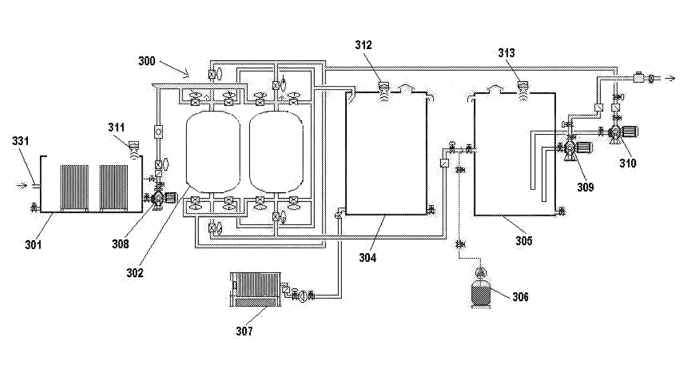
[0005]The invention relates to methods and apparatuses for the decontamination of fluid, particularly the removal of heavy metals and / or arsenic and / or their compounds from water, by means of electrolysis, wherein the water to be purified is subjected to electrodes of different polarities. The invention can include means for control of the pH of the fluid. The invention can also reduce the “hardness” of water by reducing the concentration of constituents such as calcium, magnesium, or alkalinity in water. The invention can also include control systems that allow self-cleaning of electrodes, self-cleaning of filters, and automatic monitoring of maintenance conditions.
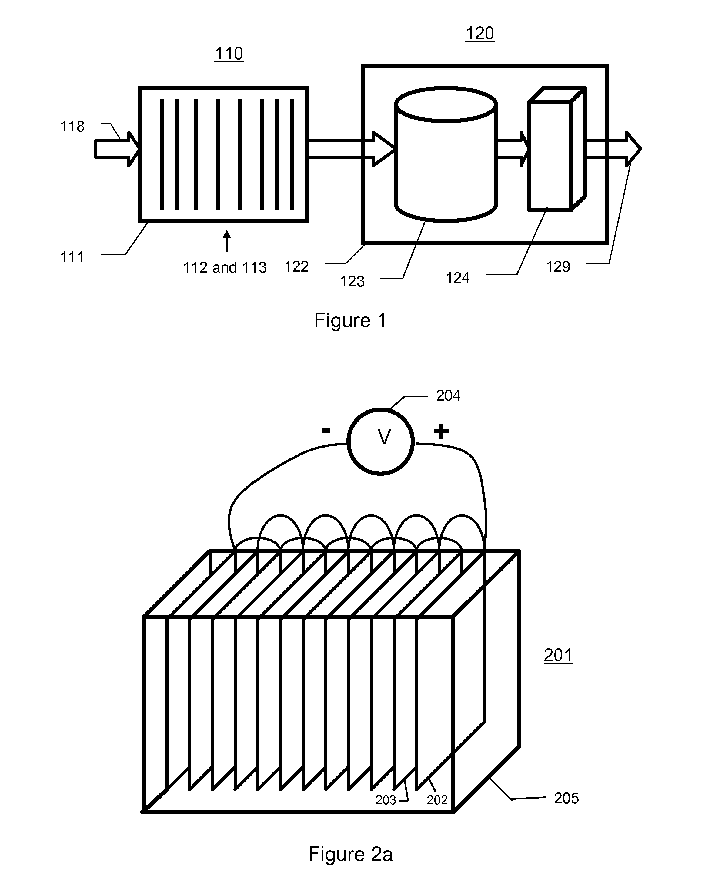
[0006]A method of the present invention for removing a contaminant from a fluid can comprise providing an anode and a cathode; placing the fluid in contact with the anode and the cathode; providing an electrical voltage between the anode and the cathode, wherein the electrical voltage is such that current flows between the anode and cathode through the fluid and forms floc by electrochemical combination of material from the anode with the contaminant; and removing at least some of the floc from the fluid. The anode preferably comprises at least 95% pure aluminum and, more preferably, at least 99% pure aluminum. The cathode can comprises iron, aluminum, carbon, or alloys thereof. The step of providing the electrical voltage can comprise providing an electrical voltage at a first polarity for a first time, then providing an electrical voltage at a second polarity, opposite the first polarity, for a second time. The first time can end when a determined increase in the electrical voltage required to maintain a minimum current through the fluid is detected. Alternatively, the first time can end when an increase in the resistivity between the anode and the cathode is detected. The magnitude of the electrical current can be an indication of the floc produced. The step of removing at least some of the floc from the fluid can comprise passing floc-laden fluid through a filter. The method can further comprise returning at least some of the floc to the fluid in an electrical current flow path between the anode and the cathode. The method can further comprise sensing the electrical voltage and current, and providing a maintenance signal based on a combination of the voltage and current. The method can further comprise agitating the anode, cathode, or both, in a manner that encourages precipitate formed on the anode, cathode, or both to dislodge therefrom. The method can further comprise providing a pH-anode comprising carbon; placing the fluid in contact with the pH-anode and the cathode; and providing an electrical voltage between the pH-anode and the cathode, where the electrical voltage is such that current flows between the anode and cathode through the fluid and reduces the pH of the fluid.
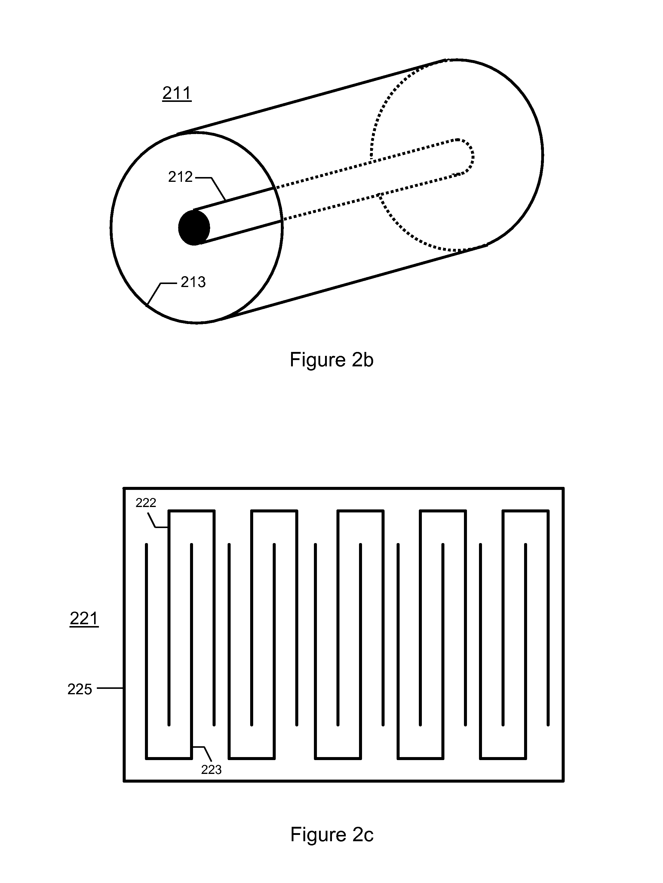
[0011]The reactor container can have electrodes mounted therein and be suitable for containing contaminant-laden fluid. The electrodes can be energized by applying an electrical potential across them, contributing to an electrolytic reaction with the contaminants. The electrolytic reaction produces a combination of electrode material and contaminant, resulting in floc which can be removed by filtering.
[0013]Contaminants in the fluid can also adhere to the non-consumed electrodes, reducing the performance of the reactor. The electric potential can be reversed in polarity periodically. By reversing the polarity, the electrodes that had been subject to contamination are converted to electrodes that are consumed in the reaction. Consumption of electrode material can remove contamination from the electrode surface, allowing the reactor to be to some extent self-cleaning.

Problems solved by technology

The growing demand on existing water sources is forcing the evaluation of previously unusable water sources for domestic needs.

Method used


Image

  • Method and Apparatus for Decontamination of Fluid with One or More High Purity Electrodes
  • Method and Apparatus for Decontamination of Fluid with One or More High Purity Electrodes
  • Method and Apparatus for Decontamination of Fluid with One or More High Purity Electrodes

Examples


Embodiment Construction

Method of Decontaminating Fluid

[0020]The present invention provides methods and apparatuses that facilitate the removal from water or other low-conductivity fluid of arsenic, heavy metals, hydrocarbons, tensides, phosphates, dies, suspended substances, toxic substances, electrochemically cleavable substances, and their compounds. The present invention can also reduce CSB-values and strip out chlorine and aromatics; even stubborn bacteria cultures such as vibrio cholera and enterococcus faecium can be extinguished and filtered out later. The present invention can also neutralize scents. Unlike previous approaches, the present invention does not require the use of membranes, chemicals, micro filtration, or specialty materials or alloys for anodes and cathode construction. The present invention can be realized with simple construction methods, and is flexible enough to support a variety of design options.

[0021]The present invention can be used in open system, partially open system, and...


PUM

PropertyMeasurementUnit
Fractionaaaaaaaaaa
Fractionaaaaaaaaaa
Flow rateaaaaaaaaaa

Abstract

The invention relates to methods and apparatuses for the decontamination of fluid, particularly the removal of heavy metals and / or arsenic and / or their compounds from water, by means of electrocoagulation followed by adsorption, wherein the water to be purified subjected to electrodes of different polarities. The invention can include means for control of the pH of the fluid. The invention can also include control systems that allow self-cleaning of electrodes, self-cleaning of filters, and automatic monitoring of maintenance conditions.

Description

CROSS-REFERENCE TO RELATED APPLICATIONS [0001]This application claims the benefit of U.S. Provisional Application 60 / 867,584, filed Nov. 28, 2006; and is a continuation-in-part of U.S. application Ser. No. 11 / 398,369, filed Apr. 5, 2006; and is a continuation-in-part of U.S. application Ser. No. 11 / 099,824, filed Apr. 6, 2005, which is a continuation-in-part of U.S. application Ser. No. 10 / 243,561, filed Sep. 12, 2002, which claims the benefit of U.S. Provisional Application No. 60 / 368,026, filed Mar. 27, 2002, each of which is incorporated herein by reference.BACKGROUND OF THE INVENTION [0002]The present invention relates to methods and apparatuses for the decontamination of water, particularly of arsenic, heavy metals, hydrocarbons, tensides, phosphates, dies, suspended substances, toxic substances, other electrochemically cleavable substances and their compounds, by means of electrolysis. In addition, the present invention can reduce CSB-values and can strip out chlorine and arom...

Claims


Application Information

Patent Timeline
IPC IPC(8): C02F1/461B01J19/08
CPCC02F1/001C02F1/463C02F2001/46133C02F2101/103C02F2101/20C02F2209/42C02F2201/4613C02F2209/03C02F2209/05C02F2209/22C02F2209/40C02F2201/46125
Inventor KLOSE, GISELHERHUANG, FRANK
Owner KLOSE GISELHER
Learn More