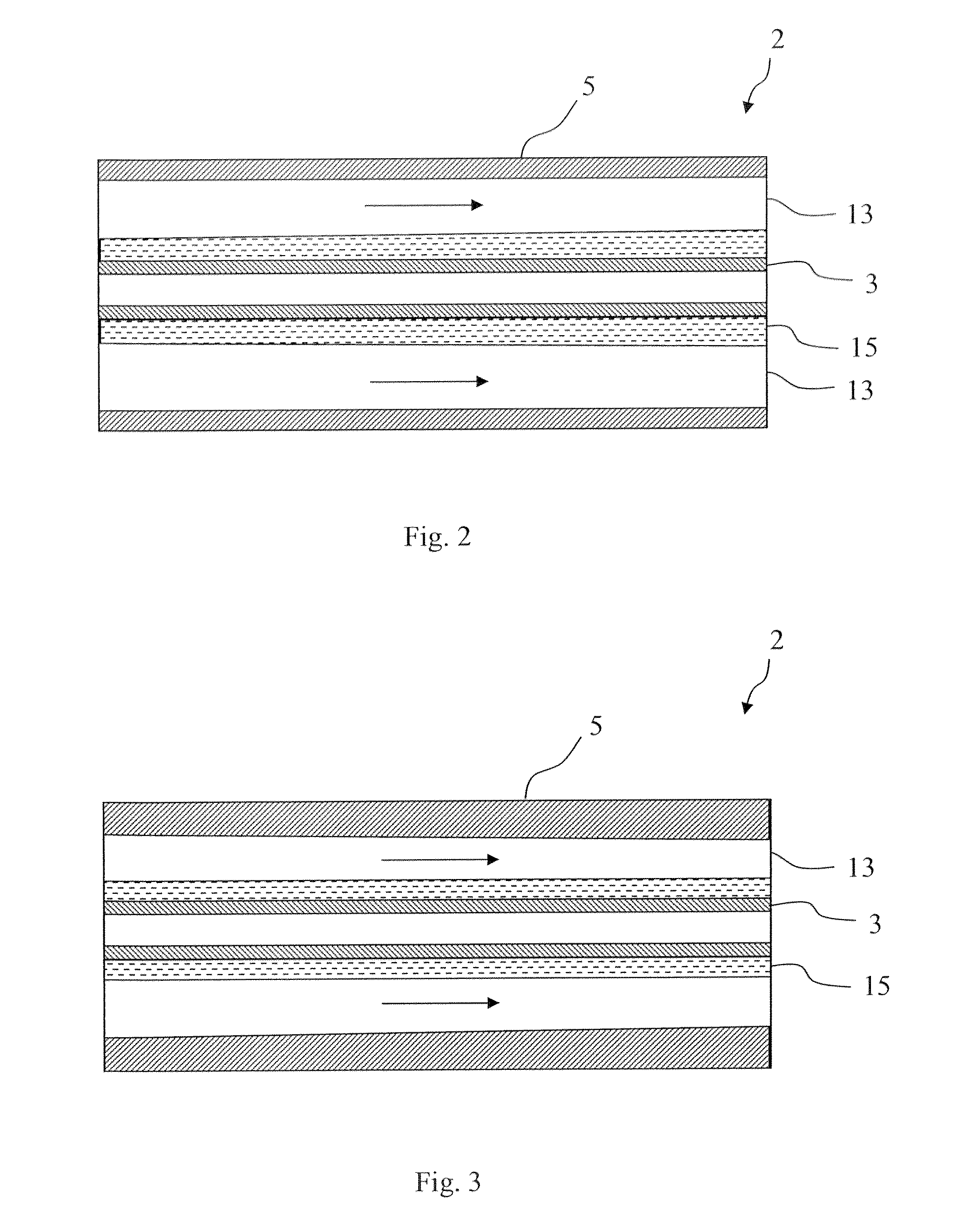
Ozone Generator

a generator and ozone technology, applied in the field of ozone generators, can solve the problems of dust formation in the form of metal oxides, local temperature excesses, and deterioration of efficiency with increasing temperature, and achieve the effects of reducing gap width, cross-sectional, and increasing flow velocity

Active Publication Date: 2008-08-14
DEGREMONT SOC DITE
View PDF4 Cites 8 Cited by
  • Summary
  • Abstract
  • Description
  • Claims
  • Application Information

AI Technical Summary

Benefits of technology

[0012]A further advantage of the decreasing gap width is that the cross-sectional area of the ozonizing gap decreases toward the outlet area. This leads to an increasingly higher flow velocity. Thus, the gas to be ozonized flows all the quicker the more ozone it contains. In this way, the effect of degradation processes on the ozone generation can be reduced. Degradation processes of this type result, for example, from flashbacks of ions from the surface of the electrodes which, in turn leads to a dust formation in the form of metal oxides. This effect is also called a sputtering effect. The dust formation leads to a dust covering of the electrode opposite the dielectric layer which, in turn, limits the ozonization gap capacity.
[0013]With a constant layer thickness or constant dielectric capacity, after the ozone generator has run in, the local weighting of the power absorption is too low or there is no local weighting of the power input, so that a substantial increase in efficiency cannot be obtained. By reducing according to the invention the dielectric capacity and / or increasing the layer thickness of the dielectric layer toward the outlet and reducing the gap width, the power absorption is locally weighted by the ozone generator. These steps, taken alone or in combination, advantageously lead to a stabilization of the power consumption and thus to a shortening of the intake time of the ozone generator.
[0014]To reduce the so-called sputtering effect, nitric oxide, in particular N2O5, is generally added to the gas to be ozonized. The nitric oxide leads to an additional emission of UV light which, in turn, leads to more unrestrained discharges, so that the voltage level of the operating voltage can be lowered. Furthermore, the nitric oxides include the metal oxides and in this way prevent the formation of dust. Thus, as a result of the nitric oxide, a passivation of the metal oxides deposited as dust on the surfaces of the electrodes takes place.
[0015]In the ozone generator according to the invention, a locally weighted power consumption takes place in that the gap width decreases toward the outlet and the dielectric capacity decreases in direction of flow of the gas and / or the layer thickness of the dielectric increases. Due to the locally weighted power consumption of the ozone generator, the effect of the surface of the electrodes decreases and the robustness of the ozone generator can be increased via the weighting of the power consumption. For example, the advantage of this is that less nitrogen or nitric oxide is required for the passivation of the metal oxides deposited on the surfaces of the electrodes. It can, for example, be sufficient to use nitrogen in an order of magnitude of 2000 ppm. Furthermore, the running-in period of the ozone generator can be reduced to less than 12 hours, whereas it is more than 500 hours in conventional ozone generators with a constant ozonization gap, constant dielectric capacity and constant layer thickness of the dielectric layer.
[0016]Even in non-ideal operating conditions, the ozone generator according to the invention behaves robustly and enables a problem-free or largely problem-free operation, also at ozone concentrations which can be above the ozone concentrations which are conventional in ozone generators with constant gap width, constant dielectric capacity and constant layer thickness of the dielectric layer. Non-ideal conditions comprise, for example, nitrogen deficiencies, pressure surges, ozone concentrations close to the poisoning limit, a high dew point or a high temperature of the condensation and / or increased traces of hydrocarbons in the gas to ozonized. A high dew point and the presence of traces of hydrocarbons in the gas to be ozonized lead to a wetting of the surfaces of the electrodes in the ozonizing gap. The result of this wetting of the electrodes is that the ozone generator begins to pulsate independently. The term “pulsating” refers to the occurrence of a series of recurrent, similar pulses or sparks. As there is a locally weighted power consumption in the ozone generator according to the invention, the effect of the pulsation on the efficiency can be reduced.

Problems solved by technology

On the other hand, with greater ozone concentrations, the efficiency deteriorates with increasing temperature.
The supply of energy into the so-called discharge channels leads to local, momentary temperature excesses.
Degradation processes of this type result, for example, from flashbacks of ions from the surface of the electrodes which, in turn leads to a dust formation in the form of metal oxides.
The dust formation leads to a dust covering of the electrode opposite the dielectric layer which, in turn, limits the ozonization gap capacity.
With a constant layer thickness or constant dielectric capacity, after the ozone generator has run in, the local weighting of the power absorption is too low or there is no local weighting of the power input, so that a substantial increase in efficiency cannot be obtained.
Due to the locally weighted power consumption of the ozone generator, the effect of the surface of the electrodes decreases and the robustness of the ozone generator can be increased via the weighting of the power consumption.
A high dew point and the presence of traces of hydrocarbons in the gas to be ozonized lead to a wetting of the surfaces of the electrodes in the ozonizing gap.

Method used


Image

  • Ozone Generator
  • Ozone Generator
  • Ozone Generator

Examples


Embodiment Construction

[0030]In FIG. 1, an ozone generator is shown by way of example which comprises a housing 1 in which a number of essentially tubular electrode arrangements 2 is provided. Each electrode arrangement 2 has an inner electrode 3 and a tubular outer electrode 5 which is arranged concentrically about the inner electrode 3. The inner electrode 3 is arranged on several essentially cylindrical electrode supports 4 arranged behind one another seen in direction of flow of the gas. The inner electrodes 3 are connected with a high-voltage alternating-current source 6. The outer electrodes 5 are grounded. The gaps 7 between the electrode arrangements 2 are rinsed by cooling water which is supplied via an inlet line 8 and removed via an outlet line 9. The oxygen-containing gas to be ozonized, which can also be pure oxygen, is supplied via an opening 10 into an inlet area or input area 11 of the ozone generator, from where it flows through the ozonizing gap 13 formed between the inner electrodes 3 a...


PUM

PropertyMeasurementUnit
gap widthaaaaaaaaaa
gap widthaaaaaaaaaa
gap widthaaaaaaaaaa

Abstract

The invention relates to an ozone generator, comprising two electrodes and a dielectric layer arranged between the above such that between the dialectic layer and one of the electrodes an ozonizing gap is formed, through which an oxygen-containing gas can be run. In the direction of the flow of the gas, a dielectric capacity (CD) of the dielectric layer of the gas becomes smaller and/or layer thickness of the dielectric layer becomes greater, such that a gap width of the ozonizing gap is greater on the inlet side than the outlet side.

Description

REFERENCE TO RELATED APPLICATIONS[0001]The application claims the priority of the international patent application PCT / CH2005 / 000458 which was filed on Aug. 3, 2005 and the contents of which are herewith included in this application.BACKGROUND[0002]The invention relates to an ozone generator comprising two electrodes and a dielectric layer arranged between them according to the preamble of claim 1.PRIOR ART[0003]An ozone generator is known from the patent DE 32 20 018 C2 which comprises two tubular electrodes and a dielectric layer arranged between them which are arranged such that a gap is formed between them serving as an ozonizing gap through which an oxygen-containing gas can be conveyed. The width of the gap of the ozonizing gap is smaller on the inlet side than on the outlet side.
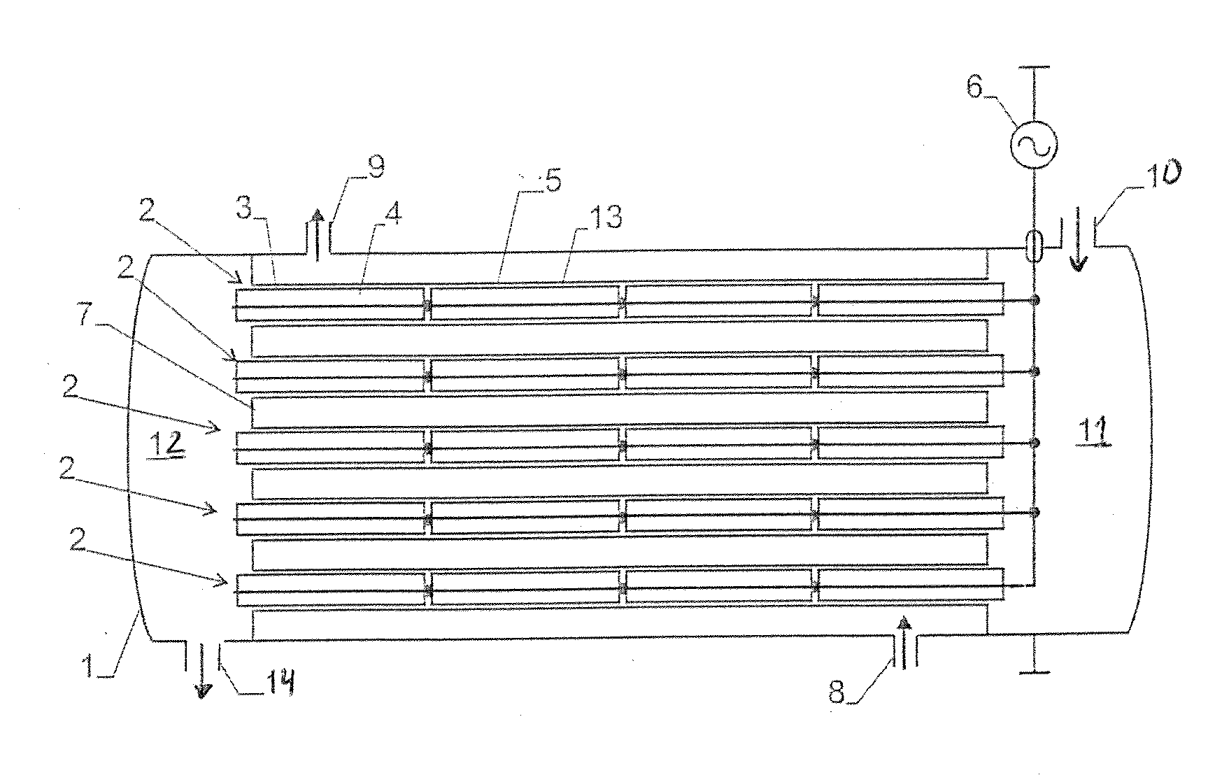
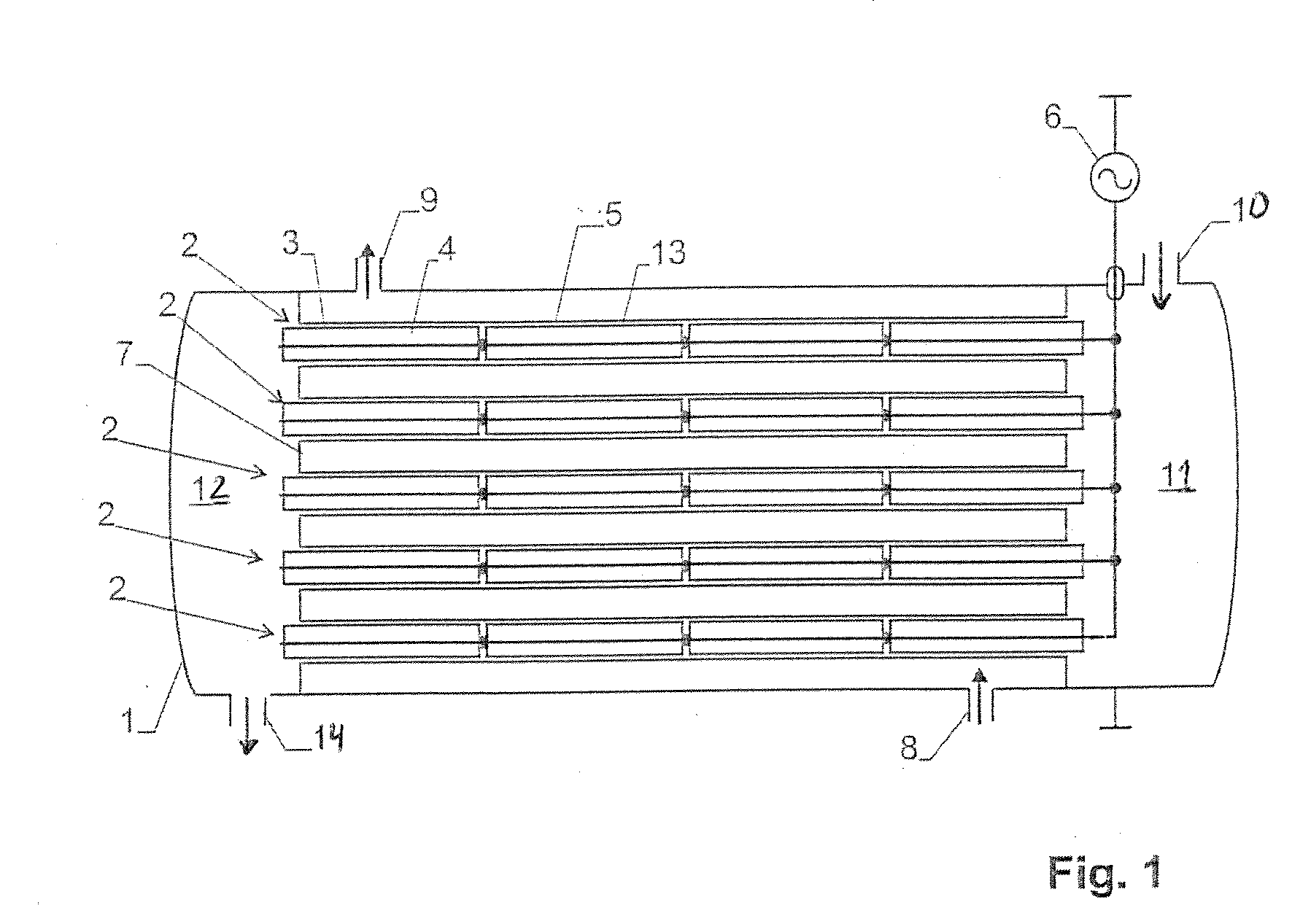
 The capacity of the dielectric can become smaller in direction of flow of the oxygen-containing gas.[0004]The object of the present invention is to create an ozone generator having good efficiency. T...

Claims


Application Information

Patent Timeline
Patent Type & Authority Applications(United States)
IPC IPC(8): C01B13/11
CPCC01B13/11C01B2201/32C01B2201/22C01B2201/14
Inventor VEZZU, GUIDO
Owner DEGREMONT SOC DITE
Why Eureka
Try Eureka